
Platform supporting device for automatic elevator mounting equipment

An automatic installation and support device technology, applied in the direction of lifting devices, etc., can solve the problems of shaking of the working platform, increase of construction difficulty, increase of construction error, etc., achieve consistent tension force, good positioning and locking effect, and reduce construction difficulty Effect

Active Publication Date: 2021-07-20
广州明森合兴科技有限公司
View PDF3 Cites 1 Cited by
  • Summary
  • Abstract
  • Description
  • Claims
  • Application Information

AI Technical Summary

Problems solved by technology

[0003] However, in the process of guide rail installation, the hoist is usually used to drive the working platform to move up and down to drive the construction equipment or construction personnel on the working platform to a specific installation height to complete the installation of the guide rail; but in this installation process, the working platform is easy During the construction process, it is shaken by the reaction force, which increases the difficulty of construction and increases the construction error.

Method used


Image

  • Platform supporting device for automatic elevator mounting equipment
  • Platform supporting device for automatic elevator mounting equipment
  • Platform supporting device for automatic elevator mounting equipment

Examples


Embodiment 1

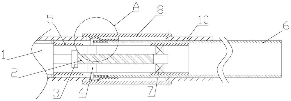
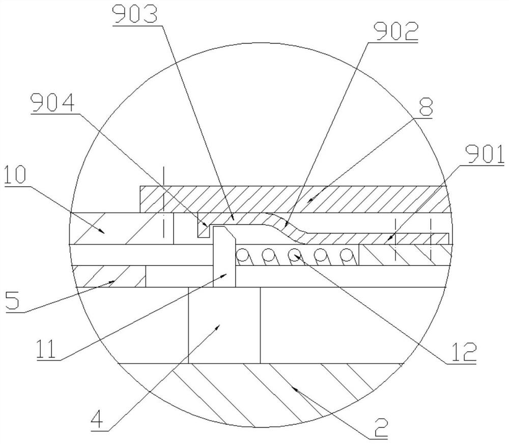
[0025] see Figure 1-Figure 3 The platform support device for elevator automation installation equipment of the present invention includes a support rod 6 arranged on the frame 10 of the working platform and a support and Lock the drive mechanism.

[0026] see Figure 1-Figure 3 , the supporting and locking driving mechanism includes a driving member 11 and a linear driving mechanism for driving the driving member 11 to perform a linear motion, wherein the supporting rods 6 are in two groups and are respectively located on both sides of the frame 10 The driving parts 11 are two groups, and the two groups of driving parts 11 are respectively connected with the two groups of support rods 6 through springs 12, one end of the spring 12 acts on the driving parts 11, and the other end acts on the On the support rods 6; each group of support rods 6 is provided with a locking member 9, and the frame 10 is provided with a groove for avoiding the locking member 9, and the groove is al...

Embodiment 2

[0038] see Figure 4 , The difference between this embodiment and Embodiment 1 is that there are two frames 10, and the two frames 10 are used to guide the support rods 6 on both sides respectively. This has the advantage that the frames 10 can be saved. materials, thereby saving costs.


PUM


Abstract

The invention discloses a platform supporting device for automatic elevator mounting equipment. The platform supporting device for the automatic elevator mounting equipment comprises supporting rods and a supporting, locking and driving mechanism; the supporting, locking and driving mechanism comprises driving pieces and a linear driving mechanism; the supporting rods are arranged on a rack, and the two ends of the supporting rods extend outwards and are connected to the driving pieces separately; locking pieces are provided on the supporting rods at each end; after the linear driving mechanism drives the driving pieces to synchronously and reversely move separately so as to enable the supporting rods at the two ends of the rack to synchronously and reversely stretch out and be tightly supported on a shaft wall surface, the linear driving mechanism continues to drive the driving pieces to move, so that the locking pieces on the supporting rods abut against the rack, and the effect of fixing the working platform for installing the equipment to the shaft wall surface is achieved. According to the platform supporting device for the automatic elevator mounting equipment, the working platform can be positioned and locked when the working platform reaches a specific mounting position, so that the working platform is prevented from shaking in the construction process, and the construction precision is guaranteed.

Description

technical field [0001] The invention relates to an elevator automatic installation equipment, in particular to a platform support device for the elevator automatic installation equipment. Background technique [0002] As a means of transportation in modern buildings, elevators are used more and more with the development of society. Elevator installation engineering has become a huge industry. The installation of the elevator usually includes the following contents: installing the lifting traction device and control system of the elevator in the machine room, installing the elevator car, counterweight, guide rail and cables, floor control and protection devices in the shaft, installing the hall door, Display and parking controller, etc. The construction of the elevator in the shaft generally needs to install four guide rails first, among which, the left and right two main rails are used to guide the elevator car up and down; the two auxiliary guide rails opposite to the hal...

Claims


Application Information

Patent Timeline
Patent Type & Authority Applications(China)
IPC IPC(8): B66F11/00B66F13/00
CPCB66F11/00B66F13/00
Inventor 王开来李宇婕夏宇嫦
Owner 广州明森合兴科技有限公司
Learn More