Gear mechanism electromagnetic type sole vibration energy collector with speed change function

A vibration energy harvesting, gear mechanism technology, applied in the direction of the mechanism, electromechanical device, electric component that generates mechanical power, can solve the problems of inability to adjust the output power, low output power, low energy utilization rate, etc., and achieve high magnetic flux change. speed, increase output power, realize the effect of variable speed function

Active Publication Date: 2021-07-20
TIANJIN UNIV
View PDF4 Cites 0 Cited by
  • Summary
  • Abstract
  • Description
  • Claims
  • Application Information

AI Technical Summary

Problems solved by technology

[0003] The existing electromagnetic foot harvester mainly has the following problems: under low-frequency excitation, such as when the user walks slowly, the output power is not high, the energy utilization rate is low, and because the structure cannot be changed, the output power under different excitations cannot be adjusted. In order to adapt to different loads, it cannot meet the actual needs. Therefore, there is an urgent need for an electromagnetic plantar vibration energy harvester with variable speed adjustment function.

Method used


Image

  • Gear mechanism electromagnetic type sole vibration energy collector with speed change function
  • Gear mechanism electromagnetic type sole vibration energy collector with speed change function
  • Gear mechanism electromagnetic type sole vibration energy collector with speed change function

Examples


Embodiment Construction

[0032] The present invention will be described in detail below with reference to the accompanying drawings and examples.

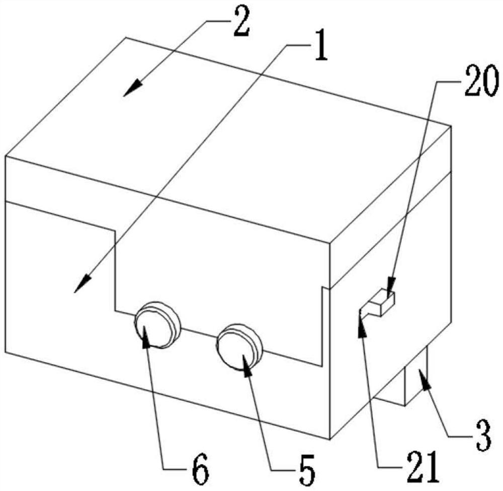
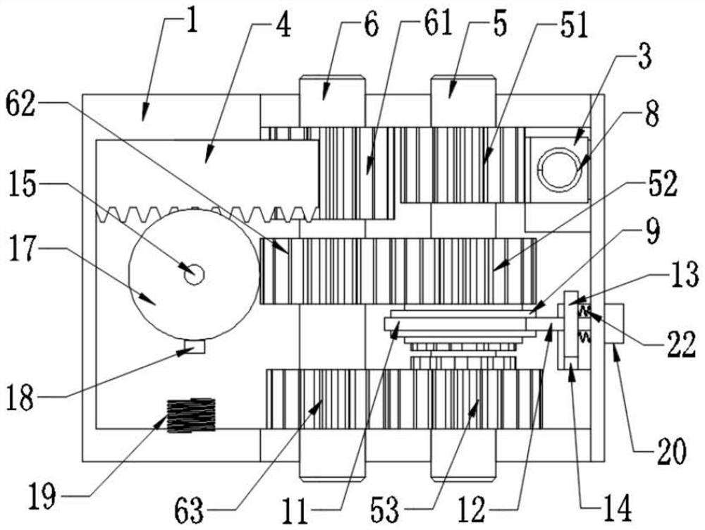
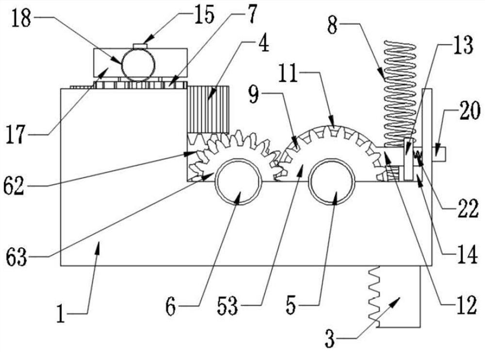
[0033] Such as Figure 1 to Figure 10 As shown, a gear mechanism electromagnetic foot vibration energy harvester with a speed change function includes a box body 1, a first rack 3 passing through the bottom surface of the box body 1 is provided at a corner of the box body 1, and the box body 1 A first rotating shaft 5 and a second rotating shaft 6 are arranged sequentially from the side of the first rack 3, and the ends of the two rotating shafts are connected to the box body 1 in rotation, and the box body 1 is laterally provided with a second rotating shaft 6 on the side of the second rotating shaft 6. Two racks 4 and a driving gear 7; the end face of the first rack 3 in the box body 1 is fixedly provided with a compression spring 8 which is against the top box cover 2 of the box body 1 .

[0034] The first rotating shaft 5 is sequentially provided with...


PUM


Abstract

The invention discloses a gear mechanism electromagnetic type sole vibration energy collector with a speed change function. The collector comprises a box body, a first rack penetrating out of the bottom face of the box body is arranged at one corner in the box body, a first rotating shaft and a second rotating shaft are sequentially arranged on the box body from one side of the first rack, and the ends of the two rotating shafts are rotationally connected with the box body; the box body is transversely provided with a second rack and a driving gear on one side of the second rotating shaft; one side of the second rack is attached to the inner wall of the box body, and the other side of the second rack is provided with insection and meshed with the driving gear; the driving gear is rotationally connected with the box body through a third rotating shaft, and anti-symmetric pawls are arranged on the top face of the driving gear; the top end of the third rotating shaft is rotationally connected with a ratchet wheel; and a magnet is fixedly arranged on the periphery of the ratchet wheel, and a coil as high as the magnet is fixedly arranged at the position, corresponding to the magnet, of the inner wall of the box body. The invention aims at providing the electromagnetic type sole vibration energy collector with the speed change adjusting function.

Description

technical field [0001] The invention relates to the technical field of vibration energy collection, in particular to a gear mechanism electromagnetic foot vibration energy collector with a speed changing function. Background technique [0002] With the improvement of living standards, people pay more and more attention to their own health. At the same time, the plantar sensor network that monitors the health and movement of the body has also attracted much attention. At present, these devices are driven by batteries, but the battery life is limited and needs to be replaced regularly, so it is impossible to achieve a "permanent" long-term operation mode. The foot sensor network integrated with vibration energy harvesting technology can realize long-term, maintenance-free and real-time condition monitoring. Vibration energy harvesting technology uses piezoelectric, electromagnetic, friction and other conversion mechanisms to convert vibration energy into electrical energy to ...

Claims


Application Information

Patent Timeline
Patent Type & Authority Applications(China)
IPC IPC(8): F03G5/06H02K7/18H02K35/02A43B3/00
CPCF03G5/06H02K35/02H02K7/1876A43B3/38
Inventor 王炜梁思楠
Owner TIANJIN UNIV
Why Eureka
Try Eureka