Supercharge Your Innovation With Domain-Expert AI Agents!

Screw vacuum pump with rotor cooling function

A rotor cooling, screw type technology, applied in the direction of rotary piston pump, rotary piston type/swing piston type pump components, rotary piston type machinery, etc., can solve the problem of consumption of external energy, poor cooling effect, increased screw vacuum pump to Energy consumption and other issues to achieve the effect of reducing resistance and reducing consumption

Active Publication Date: 2021-07-20
NANTONG BEIKE VACUUM MACHINERY CO LTD
View PDF6 Cites 0 Cited by
  • Summary
  • Abstract
  • Description
  • Claims
  • Application Information

AI Technical Summary

Problems solved by technology

[0002] When the screw vacuum pump is running normally, the gas at the exhaust port of the pump rushes back into the pump chamber to do work, and the temperature of the gas in the pump chamber rises, which makes the temperature of the pump body and rotor of the screw pump rise. In the screw vacuum pump, the rotor is set in the pump cavity. In the prior art, the cooling is done outside the pump without direct contact with the rotor, so the cooling effect is not good, and this cooling method needs to consume external energy, increasing the pump temperature. The energy consumption of the screw vacuum pump is reduced

Method used


Image

  • Screw vacuum pump with rotor cooling function
  • Screw vacuum pump with rotor cooling function
  • Screw vacuum pump with rotor cooling function

Examples


Embodiment Construction

[0021] In order to deepen the understanding of the present invention, the present invention will be further described below in conjunction with the embodiments and accompanying drawings. The embodiments are only used to explain the present invention and do not constitute a limitation to the protection scope of the present invention.

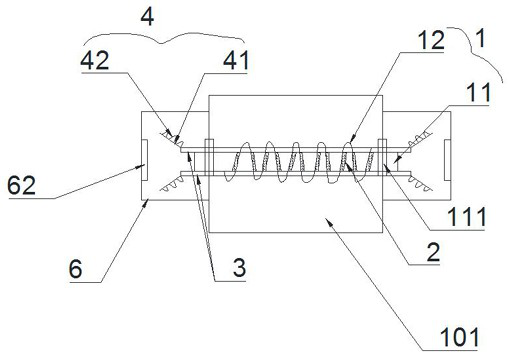
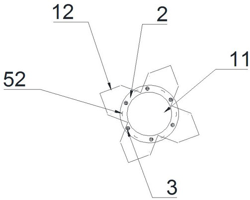
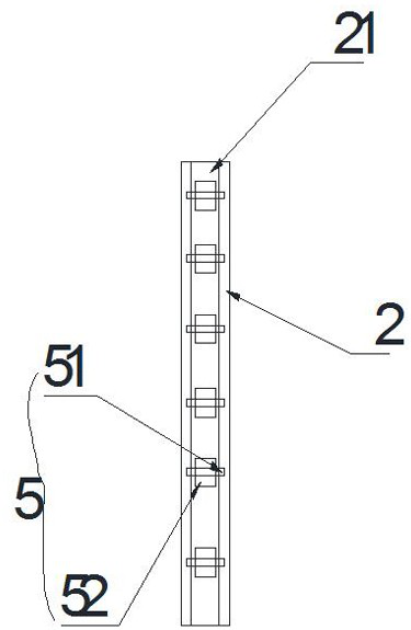
[0022] Such as Figure 1 to Figure 2 It is a specific embodiment of the present invention, and its structure includes a pump body 101. The inside of the pump body 101 is provided with a rotatable screw rod 1. The screw rod 1 includes a rotor 11 and a screw blade 12 that is screwed on the rotor 11. The rotor 11 The two ends of the pump body are rotated and installed inside the pump body 101, and the connection between the spiral blade 12 and the rotor 11 is provided with a cooling cavity 2, and the surface of the rotor 11 is horizontally distributed with a number of air guide tubes 3, and the air guide tubes 3 are connected to the cooling cavity on...


PUM


Abstract

The invention discloses a screw vacuum pump with a rotor cooling function. The screw vacuum pump structurally comprises a pump body, wherein a rotatable screw rod is arranged in the pump body, and the screw rod comprises a rotor and screw blades spirally arranged on the rotor; two ends of the rotor are rotatably arranged in the pump body, and cooling chambers are arranged at joints of the screw blades and the rotor; a plurality of air guide pipes are transversely distributed on the surface of the rotor and communicate with the interiors of the cooling chambers one by one, the interior of the rotor is hollow, and the cooling chambers communicate with the interior of the rotor; and the ends of the air guide pipes extend to the outer side of the pump body one by one, and air guide pieces are arranged at the ends of the air guide pipes. The self-cooling function of the rotor of the vacuum pump is achieved.

Description

Technical field: [0001] The invention relates to the production technical field of a vacuum pump, in particular to a screw vacuum pump with a rotor cooling function. Background technique: [0002] When the screw vacuum pump is running normally, the gas at the exhaust port of the pump rushes back into the pump chamber to do work, and the temperature of the gas in the pump chamber rises, which makes the temperature of the pump body and the rotor of the screw pump rise. In the screw vacuum pump, the rotor is set in the pump cavity In the prior art, the cooling is done outside the pump without direct contact with the rotor, so the cooling effect is not good, and this cooling method needs to consume external energy, increasing the pump temperature. Reduce the energy consumption of the screw vacuum pump. Invention content: [0003] The object of the present invention is to provide a screw vacuum pump with rotor cooling function, which can solve one or more of the above-mentione...

Claims


Application Information

Patent Timeline
IPC IPC(8): F04C18/107F04C25/02F04C29/00F04C29/04
CPCF04C18/107F04C25/02F04C29/00F04C29/04
Inventor 姚新建邓娟王旭峰
Owner NANTONG BEIKE VACUUM MACHINERY CO LTD
Features
  • R&D
  • Intellectual Property
  • Life Sciences
  • Materials
  • Tech Scout
  • Unparalleled Data Quality
  • Higher Quality Content
  • 60% Fewer Hallucinations
Learn More