Rotary dust collector floor brush structure

A vacuum cleaner and rotary technology, which is applied in the field of the floor brush structure of the rotary vacuum cleaner, can solve the problems of limiting the scope of application of the main structure of the vacuum cleaner, and achieve the effects of improving the scope of application, meeting the needs of use, and facilitating installation and disassembly.

Pending Publication Date: 2021-07-23
NINGBO HAIJI ELECTRIC APPLIANCE
View PDF0 Cites 0 Cited by
  • Summary
  • Abstract
  • Description
  • Claims
  • Application Information

AI Technical Summary

Problems solved by technology

[0003] During the use of existing hand-held vacuum cleaners, the main structure often rotates upwards in a single reverse direction centered on the ground brush of the vacuum cleaner, and the range of rotation is a fan-shaped range area. scope of application

Method used


Image

  • Rotary dust collector floor brush structure
  • Rotary dust collector floor brush structure
  • Rotary dust collector floor brush structure

Examples


Embodiment Construction

[0024] The present invention will be further described below in conjunction with the accompanying drawings and specific embodiments.

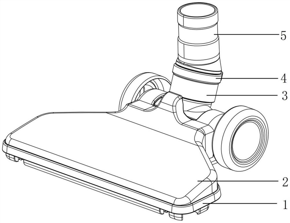
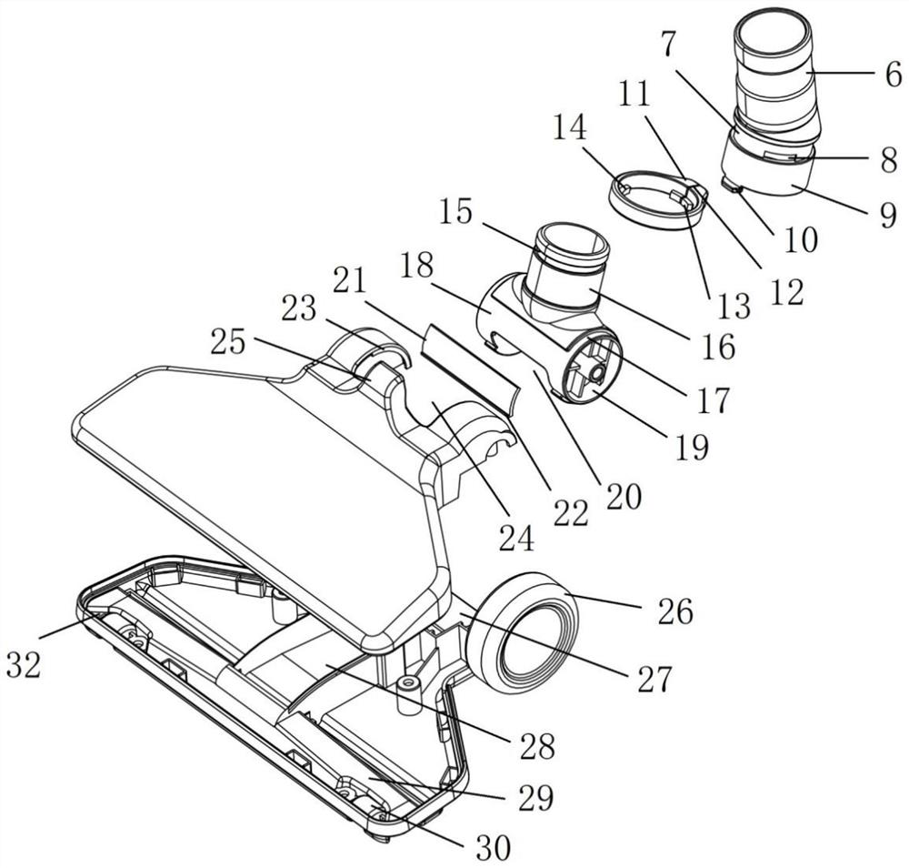
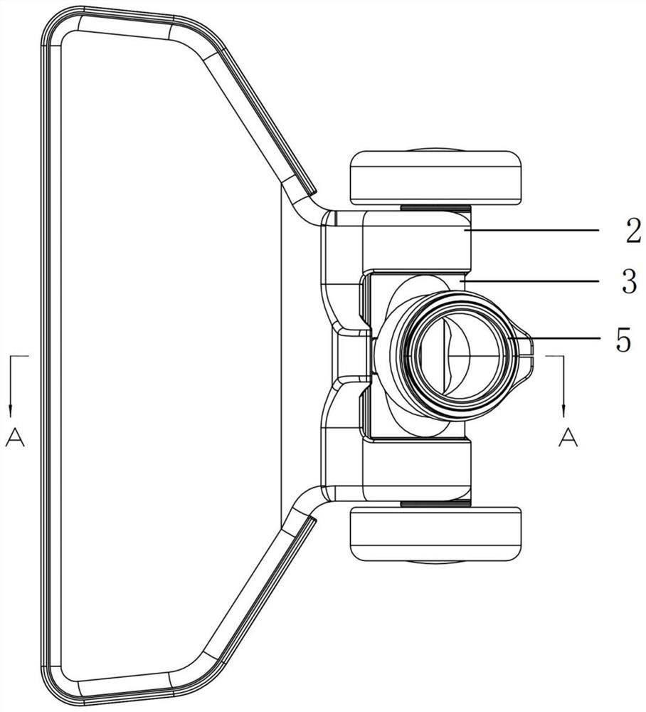
[0025] Such as figure 1 , figure 2 , image 3 In the described embodiment, a ground brush structure of a rotary vacuum cleaner includes a ground brush lower cover 1, a ground brush upper cover 2, a lower movable joint 3 and an upper movable joint 5, and the ground brush upper cover 2 is installed on the ground brush lower cover 1. The upper and lower movable joints 3 are installed between the ground brush upper cover 2 and the ground brush lower cover 1. The lower movable joint 3 is rotationally connected with the ground brush upper cover 2 and the ground brush lower cover 1. The upper movable joint 5 is installed on the lower movable joint 3, a joint collar 4 is arranged between the upper movable joint 5 and the lower movable joint 3, and the upper movable joint 5 is rotationally connected with the lower movable joint 3 through the joint co...


PUM


Abstract

The invention discloses a rotary dust collector floor brush structure. The structure comprises a floor brush lower cover, a floor brush upper cover, a lower movable joint and an upper movable joint, the floor brush upper cover is installed on the floor brush lower cover, the lower movable joint is installed between the floor brush upper cover and the floor brush lower cover, the lower movable joint is rotatably connected with the floor brush upper cover and the floor brush lower cover, the upper movable joint is installed on the lower movable joint, a connector clamping ring is arranged between the upper movable connector and the lower movable connector, and the upper movable connector is rotationally connected with the lower movable connector through the connector clamping ring. The structure has the advantages that a dust collector main machine and a dust collector floor brush can be adjusted in the vertical direction and the radial direction, the application range of the whole dust collector is greatly widened, the use requirements of different people in different environments are met, mounting and dismounting are convenient, and the dust collection effect is good.

Description

technical field [0001] The invention relates to the related technical field of vacuum cleaners, in particular to a brush structure of a rotary vacuum cleaner. Background technique [0002] Vacuum cleaners are mainly composed of three parts: dust collection, dust collection, and dust filtration, generally including series commutator motors, centrifugal fans, dust filters (bags) and dust collection accessories. The power of a general vacuum cleaner is 400-1000W or higher, and the power of a portable vacuum cleaner is generally 250W or less. The vacuum cleaner can remove dust mainly because its "head" is equipped with an electric exhaust fan. There is a wind impeller on the shaft of the exhaust fan. After power on, the exhaust fan will generate high suction and pressure at a speed of 500 cycles per second. The air in the fan is replenished in a timely manner, resulting in an instantaneous vacuum inside the vacuum cleaner, forming a negative pressure difference with the extern...

Claims


Application Information

Patent Timeline
IPC IPC(8): A47L9/00A47L5/24
CPCA47L5/24A47L9/00A47L9/009
Inventor 周荣欧阳林周骏
Owner NINGBO HAIJI ELECTRIC APPLIANCE
Why Eureka
Try Eureka