Steady-flow conveying system

A conveying system and steady flow technology, which is applied in the direction of spraying devices, coatings, and devices for coating liquid on the surface, etc. It can solve problems such as small gaps between glue applicators, changes in output flow, and changes in filter pressure. Achieve the effect of convenient overall processing and manufacturing, improved uniformity of coating, and improved product quality

A conveying system and steady flow technology, which is applied in the direction of spraying devices, coatings, and devices for coating liquid on the surface, etc. It can solve problems such as small gaps between glue applicators, changes in output flow, and changes in filter pressure. Achieve the effect of convenient overall processing and manufacturing, improved uniformity of coating, and improved product quality

CN113145407AActive Publication Date: 2021-07-23HEBEI HUASHENG PLASTIC & RUBBER MACHINERY

Image

  • Steady-flow conveying system
  • Steady-flow conveying system
  • Steady-flow conveying system

Examples


Embodiment Construction

[0020] Below in conjunction with accompanying drawing, the present invention will be further described:

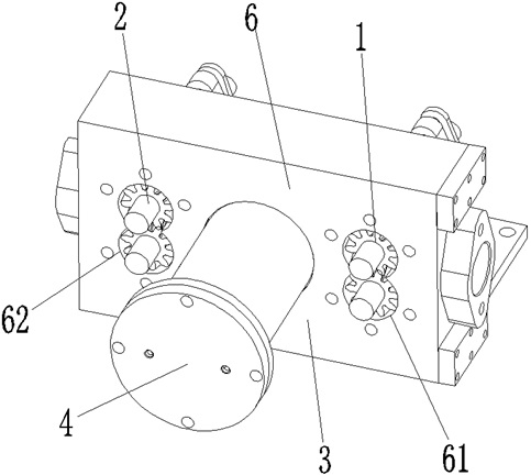
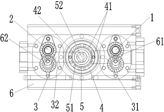
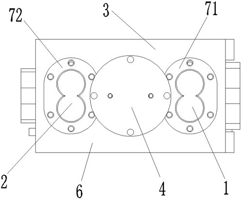
[0021] Such as figure 1 , figure 2 , image 3 , Figure 4 As shown, the steady flow delivery system includes a first pump body 1, a second pump body 2, a connecting channel 3 and a steady flow chamber 4, wherein the connecting channel 3 includes a first connecting channel 31 and a second connecting channel 32, and the steady flow The cavity 4 is provided with a steady flow inlet 41 and a steady flow outlet 42, the inlet of the first connecting channel 31 is connected with the outlet of the first pump body 1, the outlet of the first connecting channel 31 is connected with the steady flow inlet 41, and the steady flow outlet 42 It is connected with the inlet of the second connecting channel 32 , and the outlet of the second connecting channel 32 is connected with the inlet of the second pump body 2 . In this way, the inlet of the first pump body 1 is connected with the ...


PUM


Abstract

The invention discloses a steady-flow conveying system. The steady-flow conveying system comprises a first pump body, and further comprises a second pump body, a connecting channel and a steady-flow cavity, wherein the connecting channel comprises a first connecting channel and a second connecting channel; a steady-flow inlet and a steady-flow outlet are formed in the steady-flow cavity; the inlet of the first connecting channel is connected to the outlet of the first pump body; the outlet of the first connecting channel is connected to the steady-flow inlet; the steady-flow outlet is connected to the inlet of the second connecting channel; and the outlet of the second connecting channel is connected to the inlet of the second pump body. The steady-flow conveying system can continuously and stably output plaster, is uniform in plaster coating, is convenient and quick in replacing a filter screen, and is convenient in cleaning parts.

Description

technical field [0001] The invention relates to a fluid delivery device, in particular to a device for realizing constant flow delivery for fluids with high viscosity and poor fluidity. Background technique [0002] Plaster is a kind of external use of traditional Chinese medicine. Vegetable oil or animal oil is added to boil it into a gel-like substance, which is applied to one side of the substrate such as cloth, paper or leather, and sealed with release paper. Due to the high viscosity and poor fluidity of the plaster, at present, the gel-like plaster is often placed in a special container during automatic plaster processing, and a certain amount of plaster is transported to the glue applicator by a gear pump with strong self-priming force. Then apply the plaster to the base material, and then proceed to the next process until the plaster product is processed. Therefore, whether the output flow rate of the gear pump is stable directly affects whether the plaster is evenl...

Claims


Application Information

Patent Timeline
23 Jul 2021
Publication
CN113145407A
IPC
B05C11/10; B05B15/50; B05B15/55
CPC
B05C11/10; B05B15/50; B05B15/55
Inventors
胑贝贝