Hardware paint spraying and drying robot

A robot and hardware technology, applied in the direction of surface pretreatment, coating, and liquid coating device on the surface, etc., can solve the problems of dry cracking of the paint surface, high temperature of hot air on the paint surface, and small surrounding heat, etc. The effect of increasing the angle, increasing the diffusion surface, and preventing reverse advance

Pending Publication Date: 2021-07-23
翁宗兵
View PDF0 Cites 1 Cited by
  • Summary
  • Abstract
  • Description
  • Claims
  • Application Information

AI Technical Summary

Problems solved by technology

[0004] The drying system of the drying robot usually uses ceramic heating tubes to generate heat, circulates the hot air in the heat pipe cavity and the outside air, and applies the hot air blown out by the drying head to the paint surface for drying operations. The blowing air is blown out in strands, and the displacement speed of the drying head is slow. It is easy to cause the paint surface directly facing the drying head to be too hot, and the paint surface will dry too quickly and crack directly, and the surrounding heat is small. Causes a large difference in the degree of drying of the paint surface

Method used


Image

  • Hardware paint spraying and drying robot
  • Hardware paint spraying and drying robot
  • Hardware paint spraying and drying robot

Examples


Embodiment 1

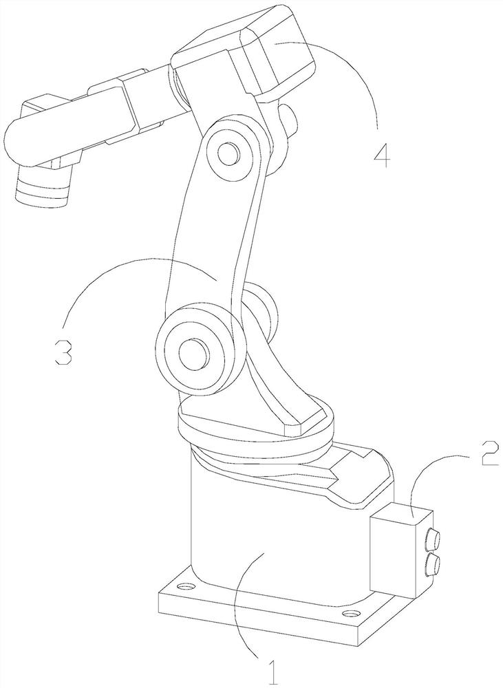
[0031] as attached figure 1 to attach Figure 6 Shown:

[0032] The invention provides a metal spraying and drying robot, the structure of which is provided with a base 1, a control box 2, a support arm 3, and a drying system 4, the control box 2 is installed on one side of the base 1, and the support arm 3 is movable Connected above the base 1, one end of the drying system 4 is hingedly connected with the support arm 3 and movably matched.

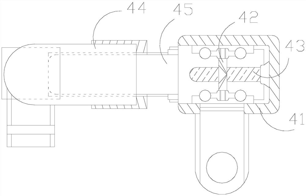
[0033] The drying system 4 is provided with a rear box 41, an air rack 42, a ceramic tube 43, a drying head 44, and a heat pipe cavity 45. The air rack 42 is embedded and installed inside the rear box 41, and the ceramic tube 43 is located In the box 41 , the heat pipe cavity 45 communicates with the rear box 41 , and the drying head 44 is movably matched with the heat pipe cavity 45 .

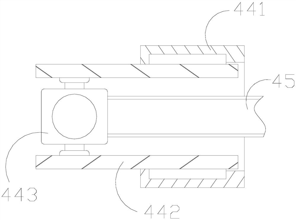
[0034] Wherein, the drying head 44 is provided with a sliding plate 441, a side plate 442, and a movable column 443, the sliding plate 441 is ring-con...

Embodiment 2

[0040] as attached Figure 7 to attach Figure 9 Shown:

[0041] Wherein, the movable ball q3 is provided with a weight q31, a variable ring q32, and a telescopic frame q33. The variable ring q32 has a ring structure and has toughness, and can be expanded and contracted. The weight q31 has a heavy pressure, and the telescopic frame q33 can perform telescopic activities. The weight q31 is In the variable ring q32, through the telescopic elasticity of the telescopic frame q33, pressure is exerted on the variable ring q32 to make it flexibly change its own ring diameter, so that the movable ball q3 as a whole continuously expands and contracts.

[0042] Wherein, the flap opening q4 is provided with a rubber pulling edge q41, an air cushion q42, an air flow port q43, and a front plate q44, the air cushion q42 is connected between the rubber pulling edges q41, and the air flow opening q43 and the air cushion q42 are an integrated structure And located below it, the front plate q...


PUM


Abstract

The invention discloses a hardware paint spraying and drying robot, which is structurally provided with a base, a control box, a supporting arm and a drying system; the control box is installed at one side end of the base; the supporting arm is movably connected to the upper portion of the base; one end of the drying system is hinged to the supporting arm and movably matched with the supporting arm; airflow pressure is generated on a pressed block when airflow passes through, and a connecting rod is pressed to move and descend; the flexible elastic force of the connecting rod enables an auxiliary arc-shaped block to rotate and shake along with the pressure applied by the air flow above, a flexible block turns over in an arc shape under the arc shape state, a certain drainage effect is achieved on the air flow above the flexible block, hot air can be discharged out of the periphery of an air outlet more quickly, and a movable ball rolls along with the angle change of the flexible block under the driving force, and pressure is continuously applied to the flexible block to further increase the rotating and shaking angle of the auxiliary arc-shaped block, so that the airflow has a larger discharging and dispersing area, and the diffusion surface is increased to better uniformly heat a paint surface.

Description

technical field [0001] The invention belongs to the field of painting processing in hardware production, and more specifically relates to a hardware painting drying robot. Background technique [0002] Hardware components are widely seen in the field of manufactured products. They are usually painted to beautify their appearance and prevent them from embroidering in a short period of time. After painting, it is necessary to use a paint drying robot to clean the hardware The paint surface is dried to speed up the processing efficiency of hardware components. [0003] Based on the inventor's discovery above, the existing metal spraying and drying robot has the following deficiencies: [0004] The drying system of the drying robot usually uses ceramic heating tubes to generate heat, circulates the hot air in the heat pipe cavity and the outside air, and applies the hot air blown out by the drying head to the paint surface for drying operations. The blowing air is blown out in...

Claims


Application Information

Patent Timeline
Patent Type & Authority Applications(China)
IPC IPC(8): B05D3/04
CPCB05D3/0413
Inventor 翁宗兵
Owner 翁宗兵
Why Eureka
Try Eureka