Meon rubber gear and motor gearbox seat assembling equipment and operation method thereof

A technology for motor gear box seat and assembly equipment, which is applied in assembly machines, metal processing equipment, and devices for coating liquid on surfaces, etc., can solve problems such as low efficiency, many defective products, and complex assembly mechanisms, and improve work efficiency , The effect of increasing the transfer speed, improving the assembly accuracy and assembly accuracy

Pending Publication Date: 2021-07-23
深圳市合利士智能装备有限公司
0 Cites 1 Cited by

AI-Extracted Technical Summary

Problems solved by technology

[0002] With the rapid development of high-end industrial product processing technology at home and abroad and the increasingly fierce market competition, controlling product quality has become the common pursuit of all enterprises, especially micro gear assembly equipment, which needs to pursue high-speed, efficient and precise production, but now The assembly me...

Method used

...

Abstract

The invention provides meson rubber gear and motor gearbox seat assembling equipment and an operation method thereof. The meson rubber gear and motor gearbox seat assembling equipment comprises an assembling platform, a motor gearbox seat conveying belt, a motor gearbox seat transferring assembly, an oil dripping waiting station, an oil dripping assembly used for dripping oil for a motor gearbox seat , a synchronous transferring assembly, an oil dripping station, a meson vibration feeding assembly, a meson transferring assembly, a meson mounting station, a rubber gear feeding assembly, an oiling assembly for oiling the rubber gear, a rubber gear transferring assembly, a finished product transferring station and a finished product transferring assembly. According to the meson rubber gear and motor gearbox seat assembling equipment, automation is achieved in the actions of feeding, oil dripping, synchronous material transferring, assembling and oiling, the assembling precision of the meson rubber gear and a motor gearbox seat can be effectively improved, and meanwhile, the assembling speed is obviously improved, and the working efficiency is greatly improved.

Application Domain

Liquid surface applicatorsAssembly machines +1

Technology Topic

Automotive engineeringManufacturing engineering +2

Image

  • Meon rubber gear and motor gearbox seat assembling equipment and operation method thereof
  • Meon rubber gear and motor gearbox seat assembling equipment and operation method thereof
  • Meon rubber gear and motor gearbox seat assembling equipment and operation method thereof

Examples

  • Experimental program(1)

Example Embodiment

[0042] The technical solutions in the embodiments of the present invention will be apparent from the drawings in the embodiment of the present invention. It will be appreciated that the specific embodiments described herein are for explaining the invention and is not limited thereto. It will also be noted that in order to facilitate the description, only the parts associated with the present invention are shown in the drawings rather than all structures. Based on the embodiments of the present invention, those of ordinary skill in the art will belong to the scope of the present invention without all other embodiments obtained without creative labor.
[0043] The "Embodiment" mentioned herein means that the specific features, structures, or characteristics described in connection with the embodiments may be included in at least one embodiment of the invention. This phrase is not necessarily a separate or alternative embodiment of the same embodiment in the various locations in the specification, nor is an independent or alternative embodiment of other embodiments. It can be apparent to those skilled in the art that the embodiments described herein can be combined with other embodiments.
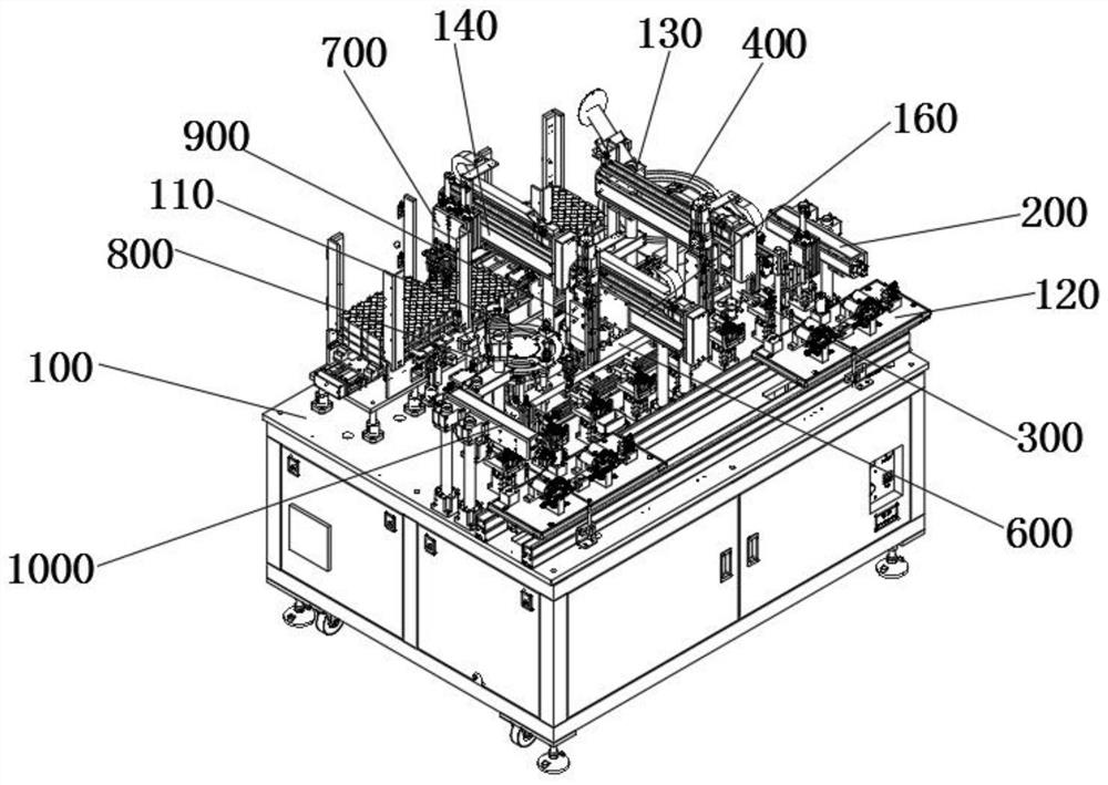
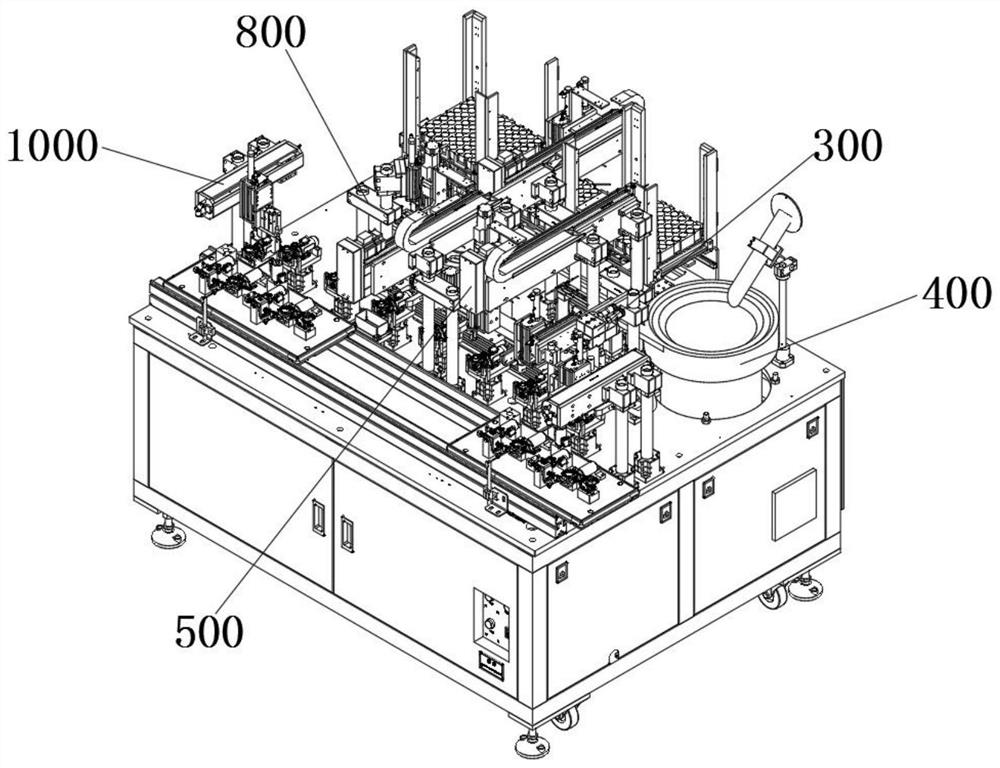
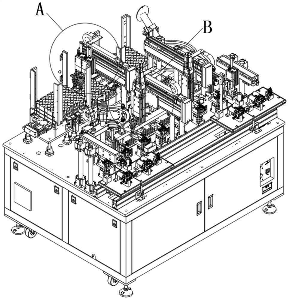
[0044] See Figure 1 to 12 , figure 1 It is a schematic structural diagram of the mesh gear and the motor cassette assembly device provided by the present invention; figure 2 It is a schematic structural diagram of an embodiment of the mesh gear and the motor casing assembly device provided by the present invention; image 3 It is a schematic structural diagram of another embodiment of the mesh gear and motor tank holder provided by the present invention; Figure 4 Yes image 3 Local enlargement map of the in the area; Figure 5 Yes image 3 Local enlargement diagram of the in-region; Image 6 It is a schematic structural diagram of an embodiment of the finished transfer assembly 1000 of the mesh gear and the motor cassette assembly device according to the present invention; Figure 7 It is a schematic structural diagram of an embodiment of the male gear gear and the motor cassette assembly apparatus provided by the present invention. Figure 8 It is a schematic structural diagram of an embodiment of the coating oil assembly 800 provided by the mesh gear and the motor assembly device according to the present invention; Figure 9 A structural diagram of an embodiment of the mesh gear and the motor assembly 700 provided by the mesh gear and the motor tank holder of the present invention; Figure 10 It is a schematic structural diagram of a mesh gear provided by the mesh gear and a motor cassette assembly device, Figure 11 It is a schematic structural diagram of the synchronous transfer assembly 600 of the mesh gear provided by the present invention and the motor assembly device; Figure 12 It is a structural diagram of the mesh transfer assembly 500 of the mesh gear and the motor cassette assembly apparatus according to the present invention.
[0045] The mesh rubber gear and motor in the present invention includes a mesh rubber gear and a motor insert assembly apparatus including an assembly platform 100, a motor tank tape 120, a motor tank holder transfer assembly 200, and a grade 150. The drip assembly 300, a synchronous transfer assembly 600, a dripping oil station 151, a mesh vibrating feed assembly 400, a mesh mounting station 152, a gear gear assembly 700, rubber gear turntable 110, used for coating oil assembly 800, rubber gear transfer assembly 900, rubber gear mounting station 153, finished transfer station 154, and finished transfer assembly 1000;
[0046] The motor box seat transmission belt 120 slides in the upper surface of the assembled platform 100, and the motor tooth chassis transfer assembly 200 is disposed between the reach oil station 150 and the motor tank seat transmission belt 120, the motor tank holder transfer assembly 200 The motor-assembled motor tape 120 is transferred from the motor to the reach 150, and the synchronous transfer assembly 600 transfer the motor to the dripper station 150 to the dripper station 151. The drip assembly 300 is disposed on the side of the motor chamber transfer assembly 200, and the dripper assembly 300 is a motor, the dripper station 151 performs drip oil, and the synchronous transfer assembly 600 will complete the motor after dripping. The tooth box is synchronized to the mesh mounting station 152;
[0047] The mesh vibrating feed assembly 400 is disposed on the assembly platform 100, and the mesh vibrating feed assembly 400 transmits the mesh vibration to the mesh transfer assembly 500, and the mesh transfer assembly 500 transfers the interroconmine from the mesh vibrating feed assembly 400 into the mesh mounting station 152;
[0048] The synchronous transfer assembly 600 transfers the product within the mesh mounting station 152 to the rubber gear mounting station 153; the rubber gear sheet assembly 700 is disposed on the assembly platform 100, and the rubber gear sheet assembly 700 transfer the rubber gear to the rubber gear. Inside the turntable 110, the rubber gear turntable 110 is rotated counterclockwise to combine the rubber gear with the coating assembly 800 to complete the oil.
[0049] The rubber gear transfer assembly 900 transferred the rubber gear completed in the rubber gear turntable 110 to the rubber gear mounting station 153, complete the assembly of the mesh gear and the motor case, and transfer the finished transfer assembly 600 to the finished product Bit 154; the finished transfer assembly 1000 is disposed at the end of the assembly platform 100, and the finished transfer assembly 1000 shifts the assembled metallo gear to the motor to the motor tape 120.
[0050] Among them, assembly platform 100 is used to carry various structural components of the present invention, that is, assembly platform 100 mainly supports various structural components;
[0051] At the same time, the motor box holder transmission belt 120 is used to carry the motor to the motor to be assembled, and the motor tape seating tape 120 slides on the assembly platform 100 to achieve automated transfer of the motor, the motor. The transfer assembly 200 clamps the motor to be assembled on the motor tape 120, and transfer the motor to the reachable motor to be dripped within 150, the synchronous transfer assembly 600 will be dropped The product in which the oil seating 150 is synchronously transferred to the dripping station 151, at this time, the drip assembly 300 enters the working state, and the drip assembly 300 is carried out on the motor mounted motor to be assembled within the dripping station 151. Drip oil, at the same time, the mesh vibration feed assembly 400 enters the working state, and the mesh vibration to be assembled is to the position corresponding to the mesh transfer assembly 500, and then the mesh transfer assembly 500 transfer the meson to the mesh mounting station 152 At this time, the synchronous transfer assembly 600 shifts the product after the dropping oil to the mesh mounting station 152 and is assembled with the mesh mounting. At this time, the rubber gear sheet assembly 700 performs the upper operation of the rubber gear and passes through the oil assembly 800. Coating oil treatment, then, the rubber gear transfer assembly 900 transferred into the rubber gear to the rubber gear mounting station 153, thereby completing the assembly, at this time, the finished transfer assembly 1000 pair of mesh rubber gears and motor teeth completed The cabinet is transferred to the motor tape 120 in the reach of the reachaes, so that the motor is continuously automated, and the automated assembly process is completed.
[0052] In the present embodiment, the motor case transfer assembly 200 includes a first driving cylinder 210, a first cylinder connecting member 220, a first vertical drive cylinder 230, a first cylinder skater 240, a first transfer plate 250, and a first clamping. The control cylinder 260 is controlled on the side wall of the first driving cylinder 210, and the first vertical drive cylinder 230 is fixed to the first air cylinder connection 220, and the first cylinder skateboard 240 is slidably connected to the first vertical drive. The sidewall of the cylinder 230, the first transfer plate 250 is fixed to the first cylinder slide 240, and the first clamping control cylinder 260 is fixed to the first transfer plate 250;
[0053] Wherein, the first cylinder joint 220 slides on the first driving cylinder 210 to move the first vertical drive cylinder 230 together, and the first vertical drive cylinder 230 drives the first clamping control cylinder 260 to achieve positional adjustment in the horizontal direction. When the first vertical drive cylinder 230 enters the working state, the output of the first vertical drive cylinder 230 drives the first cylinder skateboard 240 to move up and down, so that the first transfer plate 250 moves with the first cylinder skateboard 240, thereby achieving the first The clamping control cylinder 260 is adjusted in the vertical direction, and the first clamping control cylinder 260 can realize clamping or relaxation of the motor.
[0054] Further, when the motor tuber transfer assembly 200 needs to transfer the motor to the motor tape seat transmission belt 120 to the to-standing oil station 150, first, the first cylinder joint 220 is in the first driving cylinder. 210 slide, so that the positional change in the horizontal direction can be achieved, and the upper and lower motion motion of the first vertical drive cylinder 230 can realize the positional conversion of the vertical direction of the first transfer plate 250, so that the first transfer plate 250 drives the first clamping. The control cylinder 260 reciprocates in the vertical direction, thereby achieving clamping or relaxation of the motor tank holder, thereby enabled the motor tooth chamber transfer assembly 200 to achieve a motor to the motor tape 20 on the motor. It is within 150 of the drip oil.
[0055] In the present embodiment, the dripper assembly 300 includes a dripper fixing plate 310, a drop of dripping oil, and a flow rate adjustment rotating shaft 321, a first oil portion 330, a horizontal adjustment member 331, a drop of drip-flowing air-driven cylinder. 340, the vertical adjustment member 341, the drip adjusted plate 350, the drip joint 360, and the oil supply pipe 370, the solenoid valve 320 is fixed to the side of the dripper fixing plate 310 near the side of the motor insertion cassette transfer assembly 200, the flow adjustment rotation shaft 321 Turning one end of the solenoid valve 320, the first oil portion 330 is fixed to the lower side of the solenoid valve 320, and the solenoid valve 320 is held in communication with the first oil portion 330, and the drip oil horizontally drives the cylinder 311 to fix the connection in the dripper fixation plate. On one side opposite to the solenoid valve 320, the horizontal adjustment member 331 is slidably connected to the dripper horizontal driving cylinder 311, and the drip oil vertically drives the cylinder 340 fixed to the horizontal adjustment member 331, and the vertical adjustment member 341 slides the connection in the drop of drip oil vertical drive On the side wall of the cylinder 340, the dripper adjustment plate 350 is fixed to the vertical adjustment member 341, and the drip joint 360 is disposed at the lower end of the vertical adjustment member 341, and the oil supply pipe 370 is fixed to the outside of the drip joint 360.
[0056] Among them, the motor chamber is transferred to the oil-proof station 150, the dripper assembly 300 performs drops of dripper, and the first oil supply portion 330 is connected to the external oil supply device, thereby introducing oil into the first Inside the oil portion 330, the oil entering the first oil portion 330 proceeds into the oil supply pipe 370, which in turn into the drip joint 360, at which time, the horizontal adjustment member 331 drives the cylinder 311 at the drop of the oil. The output shaft slides so that the drip joint 360 is matched to the position of the tuber station 150, and then the drip oil vertically drives the cylinder 340 to enter the operating state, so that the vertical adjustment member 341 is vertically driven in the drip oil vertical direction. Sports, thereby moving with the vertical adjustment member 341, so that the dripper adjustment plate 350 drives the dripper joint 360 to access the dripping oil station 150, so that the drip joint 360 is fixed in a stationary oil. The motor in the 150 is carried out, and after completing the drip fuel to the motor case, the drip oil vertically drives the cylinder 340 to drive the dripper joint 360 away from the oil level 150.
[0057] In the present embodiment, the dripper adjusting plate 350 is fixed to the detection fixing plate 380, and the detecting the fixing plate 380 is fixed to the detection of a dripper detecting sensor for detecting whether the motor tooth chaler is uniform.
[0058] Among them, the dripper detection sensor can sense detection of motor induction in the motor box in real time to confirm that the drip oil is sufficient to ensure the quality of the drip oil.
[0059] In the present embodiment, the mesh transfer assembly 500 includes a mesh transfer portion 130, a mesh transfer horizontal slide plate 510, a mesh transfer vertical driving cylinder 520, a mesh transfer vertical slide plate 530, a mesh transfer plate 540, and a metastatic clamping air cylinder 550, The mesh transfer horizontal slide plate 510 slides to be connected to the side transfer portion 130 away from the side of the motor tooth casing transfer assembly 200, and the mesh transfer vertical drive cylinder 520 is fixed to the mesh transfer horizontal slide plate 510 away from the side of the mesh transfer portion 130, meonon The transfer vertical slide plate 530 and the mesh transfer vertically drive the drum 520 side wall slide, the mesh transfer connection plate 540 and the mesh transfer vertical slide plate 530 fixedly connected, and the mesh transfer clamping air cylinder 550 is fixedly disposed at the lower end of the mesh transfer plate 540.
[0060] However, when the meon vibrating feed assembly 400 is completed, the mesh transfer assembly 500 is transferred to the mesh, first, the mesh transfer horizontal slide plate 510 slides on the mesh transfer portion 130, thereby approaching the mesh vibrating feed assembly 400, then, then, The mesh transfer vertically driven cylinder 520 enters the working state, so that the drive mesh transfer the vertical slide plate 530 as a top-down reciprocating movement, and the mesh transfer vertical slide plate 530 can move the mesh transfer plate 540, so that the mesh transfer clamping air cylinder 550 is close to it. meson. At this time, the meon transfer clamping air cylinder 550 enters the working state, thereby implementing the clamping operation of the mesh, and then, the mesh transfer vertically driven cylinder 520 drives the mesh transfer vertical slide plate 530 to move upward, and the mesh transfer vertical slide plate 530 drives mesh transfer The connecting plate 540 moves upward, so that the mesh transfer clamping air cylinder 550 moves up, then the mesh transfer horizontal slide plate 510 moves on the mesh transfer portion 130, so that the mesh transfer clamping air cylinder 550 is close to the drip oil station 150, thus The dielectron is mounted to the oil-proof station 150, and then the synchronous transfer assembly 600 is transferred to the oil-filled motor to be dripped within 150.
[0061] In the present embodiment, the synchronous transfer assembly 600 includes a fixed bottom plate 610, a cylinder fixing plate 620, a synchronous transfer driving cylinder 630, a synchronous transfer clamping cylinder 640, and a fixed bottom plate 610 fixedly coupled to a plurality of standby oil position 150 side, Further, the fixed bottom plate 610 is parallel to the plurality of standby oil position 150, and the cylinder fixing plate 620 is fixedly disposed on one side of the fixed bottom plate 610 away from the assembled platform 100, and the synchronous transfer driving cylinder 630 is fixedly disposed on the cylinder fixing plate 620, synchronous transfer. The clamp hand cylinder 640 slides between the fixed bottom plate 610 and the cylinder fixing plate 620, the synchronous transfer drive cylinder 630 drives the synchronous transfer clamping cylinder 640 slides between the fixed bottom plate 610 and the cylinder fixing plate 620, so that the synchronous transfer clamp 640 Temperature is synchronously transferred to a dripper station 150, a dripping station 151, a mesh mounting station 152, a rubber gear mounting station 153, and a product in the finished transmissive station 154.
[0062] Wherein, the synchronous transfer assembly 600 is mainly used to achieve the transfer of materials between multiple stations.
[0063] Specifically, the synchronous transfer drive cylinder 630 is used to drive the synchronous transfer clamping cylinder 640 as a straight line reciprocating motion that keeps parallel with the plurality of stations, so that the synchronous transfer clamping cylinder 640 is transferred to the material.
[0064] In the present embodiment, the rubber gear sheet assembly 700 includes a rubber gear support plate 710 for placing the first station 720 of the material pallet for placing the second station 721 to be transferred to the material pallet for placement. The third station 722 of the empty material pallet is used to achieve the material transfer rail 730, a rubber gear transfer portion 140, a rubber gear transfer unit 140, a rubber gear transfer cylinder 750, a rubber gear transfer cylinder 750, a rubber gear transfer. The connecting plate 760 and the rubber gear clamp cartridge 770, the rubber gear support plate 710 fixedly disposed on the upper side of the assembly platform 100, the first station 720, the second station 721, and the third station 722 are sequentially disposed in the rubber gear support plate 710. The material transfer rail 730 is fixed from the side of the assembly platform 100, and the rubber gear transfer portion 140 is slidably coupled to the rubber gear transfer portion 140, and the rubber gear transfer cylinder 750 is fixed to the rubber gear transfer cylinder 750. The rubber gear transfer connection plate 760 is fixed to the output of the rubber gear transfer cylinder 750, and the rubber gear clamp cartridge 770 is fixed to the rubber gear transfer connection plate 760, and the rubber gear clamp cartridge 770 is adapted to the second station 721 The rubber gear transfer slide is slid on the rubber gear transfer portion 140 to achieve the transfer of the rubber gear in the material tray within the second station 721 in the rubber gear die casing 770.
[0065] Among them, the rubber gear sheet assembly 700 is used to complete the sheet action of the rubber gear. First, the material transfer rail 730 is used to achieve the transfer between the material pallet between the first station 720, the second station 721, and the third station 722, and when the rubber gear sheet assembly 700 is within the second station 721 When the rubber gear in the material pallet is placed, the rubber gear transfer slide is moved on the rubber gear transfer portion 140 such that the rubber gear transfer clamp is on the upper side of the second station 721, at this time, the rubber gear transfer cylinder 750 is driven The rubber gear transfer connection plate 760 moves downward, thereby causing the rubber gear clamp cartridge 770 to the rubber gear, and then the rubber gear transfer cylinder 750 drives the rubber gear clamp cartridge 770 to move, and then, the rubber gear transfer slide on the rubber gear The transfer portion 140 is moved on so that the gear gear clamp cartridge 770 transports the rubber gear to the rubber gear turntable 110.
[0066] In the present embodiment, the oil assembly 800 includes an oil-driven drive cylinder 810, a water driver plate 820, a second oil supply portion 830, a coating portion 831, an oil-perpendicular driving cylinder 840, a cylinder supporting seat 850, a coating rail 860, the oil-driven drive motor 880 and the oil-driven drive motor 880, the oil-driven cylinder 810 drives the oil-driven drive plate 820 to close to the rubber gear, and the second oil portion 830 is fixed to the oil-driven plate 820, the oil portion 831 The second oil portion 830 is in communication, and the oil-perpendicular driving cylinder 840 is provided in the cylinder support holder 850, the oil tide rail 860 is connected to the output shaft of the oil-shaped vertical drive cylinder 840, the oil coating plate 870 and the oil slide rail 860 Secure connection, the oil-driven drive motor 880 is fixed to the coating plate 870, and the output terminal of the oil driver motor 880 drives the rubber gear rotation on the rubber gear turntable 110, and cooperates with the coating portion 831 to complete the oil of the rubber gear. action.
[0067] Among them, the rubber gear of the rubber gear tank 110 is transferred to the rubber gear tank 110, and it is necessary to carry out the oiling operation.
[0068] Specifically, the oil-driven cylinder 810 drives the oil-driven drive plate 820 to move toward the direction near the rubber gear, so that the coating portion 831 is in contact with the rubber gear, so that the second oil supply portion 830 is connected to the external oil supply device, which in turn The coating portion 831 completes the oil to the rubber gear, and the output shaft of the oil-shaped vertically driven cylinder 840 is moved within the cylinder supporting seat 850, which can move the oil slide rail 860, and the oil slide rail 860 drives the oil-tissue plate 870. The oil-coating plate 870 is further driven by the oil-driven drive motor 880 to contact the rubber gear, and the oil driving motor 880 enters the working state such that the rubber gear of the coating drive motor 880 is rotated.
[0069]In the present embodiment, the rubber gear transfer assembly 900 includes a rubber gear lower portion 160, a rubber gear blank slide 910, a rubber gear lowering, a rubber gear pad, and a rubber gear lowering plate 930, and a rubber gear lower transfer cylinder 940. The rubber gear lower body 160 is fixed to the assembly platform 100, and the rubber gear lower plate slide 910 is slidably connected to the rubber gear lower portion 160, the rubber gear pad drives the cylinder 920 and the rubber gear blank slide 910 away from the rubber gear One side of the portion 160 is fixed, the rubber gear lowering plate 930 is fixed to the side of the rubber gear pad driving the cylinder 920 away from the rubber gear lower slide 910, the rubber gear lower transfer cylinder 940 is fixedly connected in the rubber gear The connecting plate 930 is away from the side of the rubber gear pad driving the cylinder 920, and the rubber gear lower transfer cylinder 940 completes the rubber gear die 110 to the rubber gear ordered to the rubber gear mounting station 153.
[0070] Among them, when the rubber gear transfer assembly 900 is required to transfer the rubber gear to the rubber gear turntable 110 to the rubber gear mounting station 153, first, the rubber gear blank slide 910 slides on the rubber gear lower portion 160 to make the rubber gear The lower portion transfer cylinder 940 is located on the upper side of the rubber gear turntable 110, at this time, the rubber gear lower material drives the cylinder 920 into the working state, the rubber gear pad drives the cylinder 920 to drive the rubber gear pad connecting plate 930, so that the rubber gear The transfer cylinder 940 is in contact with the rubber gear. At this time, the rubber gear lower transfer cylinder 940 is clamped by the rubber gear, and then the rubber gear pad drives the cylinder 920 to drive the rubber gear pad connecting plate 930 to move upward, so as so of the rubber gear The material driver cylinder 920 carries the gel gear down transfer cylinder 940 to move up, and then the rubber gear lower slide 910 slides on the rubber gear lower portion 160, so that the rubber gear lower transfer cylinder 940 is close to the drip oil station 150, thereby The rubber gear is completed into the rubber gear mounting station 153.
[0071] In the present embodiment, the finished transfer assembly 1000 includes a second driving cylinder 1100, a second cylinder connecting member 1200, a second vertical drive cylinder 1300, a second cylinder slide 1400, a second transfer plate 1500, and a second clamping control cylinder 1600. The second cylinder joint 1200 slides to be connected to the side wall of the second driving cylinder 1100, and the second vertical drive cylinder 1300 is fixed to the second cylinder connection 1200, the second cylinder slide 1400 and the second vertical drive cylinder 1300 output shaft Connect, the second transfer plate 1500 is fixed to the second cylinder slide 1400, and the second clamping control cylinder 1600 is fixed to the lower end of the second transfer plate 1500, and the second clamping control cylinder 1600 completes the lower body of the assembled material. .
[0072] Among them, when the finished metastatic assembly 1000 needs to transfer the assembled mesh gear to the motor chamber to the motor tape 120, first, the second cylinder connection 1200 slides on the second drive cylinder 1100, second The cylinder joint 1200 drives the second vertical drive cylinder 1300 to slide together, so that the positional conversion in the horizontal direction can be realized, the output of the second vertical driving cylinder 1300 drives the second cylinder slide 1400 to move the second transfer plate 1500 vertical. The position transform of the direction, so that the second transfer plate 1500 drives the second clamping control cylinder 1600 to reciprocate in the vertical direction, thereby achieving clamping or relaxation of the molten mean rubber gear and the motor tank holder, thereby enabling the finished product The transfer assembly 1000 can achieve a metallic gear of the assembled mesh gear on the finished transfer station 154 to the motor tape 120.
[0073] In the present embodiment, the present invention also provides an operation method of a mesh gear and a motor tooth casing assembly apparatus, and is applied to the above-described mesh gear and a motor tooth chamber, and the operation method includes the following steps: S1: Repair The reachable mutage box placed on the motor tape transfer assembly 200 will be transferred to the reort oil in the motor tape 120; S2: drip oil, the synchronous transfer assembly 600 will be placed The motor in the oil grade 150 is transferred to the dripstick station 151, and the dripper assembly 300 performs drip oil on the motor; S3: mesh transfer, the mesh transfer assembly 500 will be transported by the mesh vibrating feeding assembly 400. The mesh is transferred to the mesh mounting station 152; S4: The first assembly, the synchronous transfer assembly 600 transferred the product in the dripping station 151 into the mesh mounting station, allowing the mesh and drip oil. One assembly; S5: rubber gear transfer, the rubber gear sheet assembly 700 transfer the rubber gear into the rubber gear turntable 110; S6: rubber gear, the oil assembly 800 is applied to the rubber gear in the rubber gear core 110 Treatment; S7: The second assembly, the rubber gear transfer assembly 900 transfer the rubber gear after the oil treatment to the rubber gear station; S8: Finished, the synchronous transfer assembly 600 transfer the assembly product to the finished transfer station; S9 : Upper, the finished transfer assembly 1000 transfers the finished product in the finished transfer station to the motor tape 120.
[0074] The mesh rubber gear and the motor tooth casing assembly apparatus include assembly platform 100, motor tank holder conveyor belt 120, motor tank holder transfer assembly 200, to be dripping oil station 150 for droplets of dripping drops of motor cases Oil assembly 300, synchronous transfer assembly 600, dripping oil station 151, mesh vibrating feed assembly 400, meon transfer assembly 500, meon mounting station 152, rubber gear sheet assembly 700, is used to coat oil according to rubber gears 800, the rubber gear transfer assembly 900, the finished transfer station 154 and the finished transfer assembly 1000, wherein the present invention has automated in the above, dripper, synchronous transfer material, assembly, and oil, and can effectively improve the mesh. The assembly accuracy and assembly accuracy of the rubber gear and the motor case, at the same time, the transition speed is significantly improved, which greatly improves work efficiency.
[0075] The above embodiments are not intended to limit the patent scope of the present invention, and an equivalent structure or equivalent process transform is used to use the specification or equivalent flow of the present invention and the accompanying drawings, or use it directly or indirectly in other related technologies. The field is related to the patent protection range of the present invention.

PUM

no PUM

Description & Claims & Application Information

We can also present the details of the Description, Claims and Application information to help users get a comprehensive understanding of the technical details of the patent, such as background art, summary of invention, brief description of drawings, description of embodiments, and other original content. On the other hand, users can also determine the specific scope of protection of the technology through the list of claims; as well as understand the changes in the life cycle of the technology with the presentation of the patent timeline. Login to view more.

Similar technology patents

Report data generating method and system

ActiveCN103473342ASimplify the docking processImprove work efficiency
Owner:BEIJING JOIN CHEER SOFTWARE

Caking fertilizer crushing device for agriculture big data

Owner:安徽众力农业装备科技有限公司
Why Eureka
Try Eureka