Clamping device for hardware material machining

A material processing and clamping device technology, applied in the field of hardware, can solve problems such as processing errors, workpiece abnormalities, and workpiece waste, and achieve the effect of increasing the clamping area, improving the clamping strength, and ensuring the clamping effect

Inactive Publication Date: 2021-07-23
南京宗阳电子商务有限公司
View PDF0 Cites 0 Cited by
  • Summary
  • Abstract
  • Description
  • Claims
  • Application Information

AI Technical Summary

Problems solved by technology

[0002] History has entered the modern industrial society, and the metal-hardware industry has developed rapidly. The hardware industry has played an inestimable role in the development of the national economy. Hardware products have also become an indispensable part of industrial manufacturing. Ancillary products, semi-finished products, and tools used in the production process, etc., only a small part of daily-use hardware products are tool-like consumer goods necessary for people's lives. Most of the current hardware is passed through production and processing equipment to become workpieces of a certain size, which is convenient for later use. However, when the current processing equipment is in use, it often encounters some problems, resulting in processing errors
[0003] The current processing equipment often needs fixtures to clamp the workpiece during the processing process, but most of the current clamping tools are clamped on two sides. When clamping a regular shape, the stability of the workpiece can be guaranteed, but the clamping When holding an irregular shape, it often occurs that the clamping is not firm, resulting in abnormal movement of the workpiece during processing, resulting in errors in the processing of the workpiece, resulting in waste of the workpiece

Method used


Image

  • Clamping device for hardware material machining
  • Clamping device for hardware material machining
  • Clamping device for hardware material machining

Examples


Embodiment Construction

[0020] The following will clearly and completely describe the technical solutions in the embodiments of the present invention with reference to the accompanying drawings in the embodiments of the present invention. Obviously, the described embodiments are only some, not all, embodiments of the present invention. Based on the embodiments of the present invention, all other embodiments obtained by persons of ordinary skill in the art without making creative efforts belong to the protection scope of the present invention.

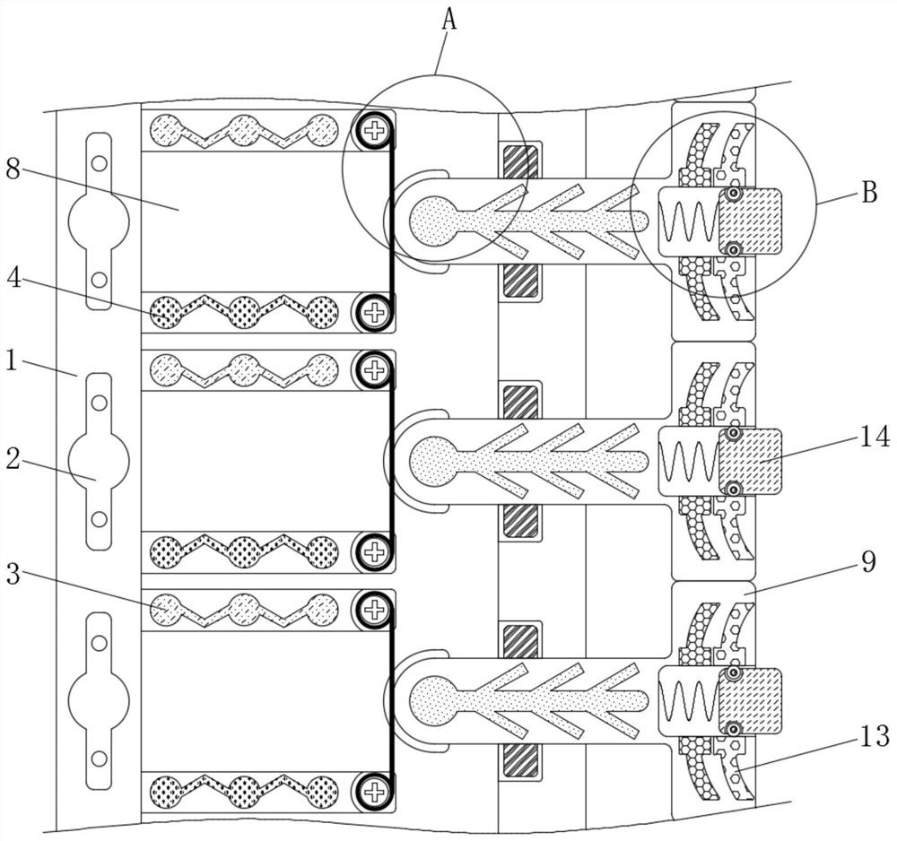
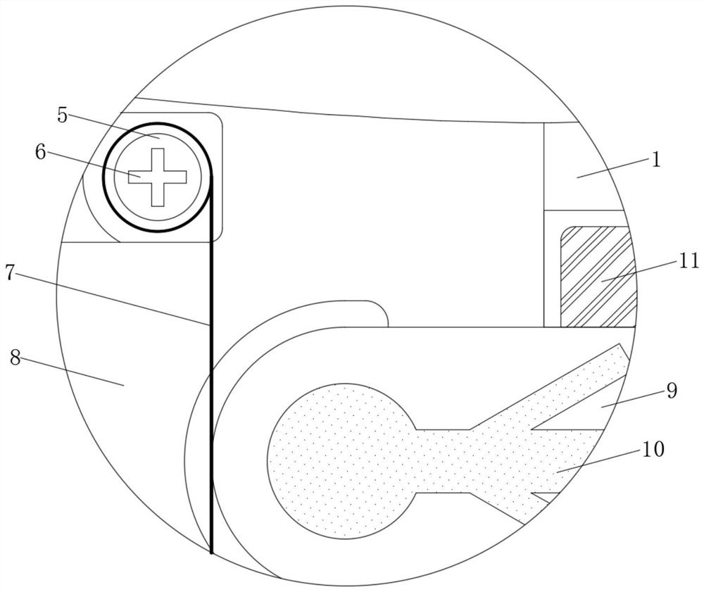
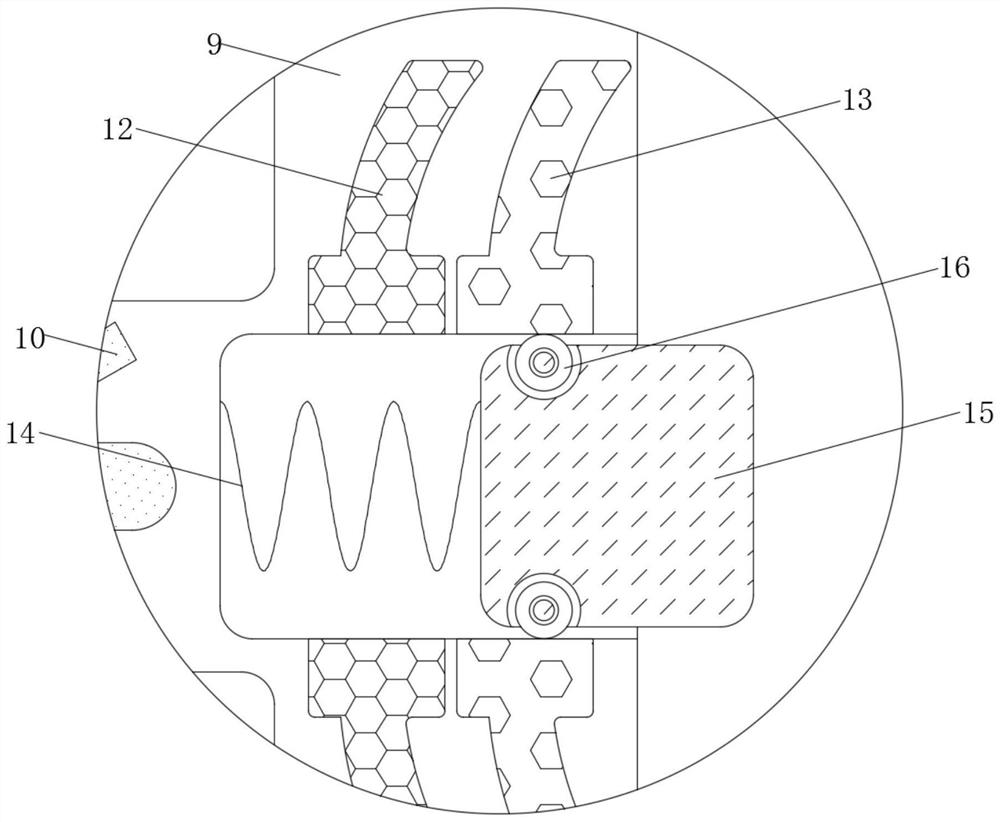
[0021] see Figure 1-5 , a clamping device for metal material processing, including a housing 1, the material of the housing 1 is a hard high-strength material and the housing 1 does not have electrical conductivity and magnetic permeability, and the housing 1 plays the role of fixing each component, The maximum path voltage of the resistor 2 is greater than the minimum circuit voltage through the negative plate 4, and the resistor 2 plays the role of controll...


PUM


Abstract

The invention relates to a clamping device for hardware material machining and relates to the technical field of hardware. The clamping device comprises a shell, the inner wall of the left side of the shell is fixedly connected with resistors, the inner wall of the shell is fixedly connected with uniformly distributed positive plates, the inner wall of the shell is fixedly connected with negative plates symmetrical to the positive plates, and the inner wall of the shell is fixedly connected with uniformly distributed winding columns. Electric heaters are fixedly connected to the inner walls of the winding columns, titanium-nickel ropes are fixedly connected to the outer sides of the winding columns, and a movable groove is formed in the middle of the shell. According to the clamping device for hardware material machining, through cooperative use of movable blocks and positioning blocks, when a clamp clamps a workpiece to be machined, the workpiece can extrude the movable blocks into the shell according to the shape of the workpiece, so that the overall shape of the movable blocks is the same as the shape of the workpiece to be machined, electrorheological fluid in the movable groove is electrified and hardened, the positioning blocks fix the positions of the movable blocks, the clamping area is increased, the clamping strength is improved, movement of the workpiece is effectively avoided, and the clamping effect is guaranteed.

Description

technical field [0001] The invention relates to the technical field of hardware, in particular to a clamping device for processing hardware materials. Background technique [0002] History has entered the modern industrial society, and the metal-hardware industry has developed rapidly. The hardware industry has played an inestimable role in the development of the national economy. Hardware products have also become an indispensable part of industrial manufacturing. Ancillary products, semi-finished products, and tools used in the production process, etc., only a small part of daily-use hardware products are tool-like consumer goods necessary for people's lives. Most of the current hardware is passed through production and processing equipment to become workpieces of a certain size, which is convenient for later use. However, when the current processing equipment is in use, it often encounters some problems, resulting in errors in processing. [0003] The current processing ...

Claims


Application Information

Patent Timeline
Patent Type & Authority Applications(China)
IPC IPC(8): B23Q3/06B24B41/06
CPCB23Q3/06B24B41/06
Inventor 唐朝
Owner 南京宗阳电子商务有限公司
Why Eureka
Try Eureka