
Accurate control system and control device for manipulator

A technology of precise control and manipulators, applied in the field of manipulators, can solve problems such as the difficulty of judging the operating status of manipulators, and achieve the effects of improving turnover quality, improving cleanliness, and improving processing quality

Active Publication Date: 2021-07-23
HANGZHOU VOCATIONAL & TECHN COLLEGE
View PDF9 Cites 5 Cited by
  • Summary
  • Abstract
  • Description
  • Claims
  • Application Information

AI Technical Summary

Problems solved by technology

[0006] In order to make up for the deficiencies of the prior art and solve the problem that it is difficult to judge the operating state of the manipulator, the present invention provides a precise control system for the manipulator and its control device

Method used


Image

  • Accurate control system and control device for manipulator
  • Accurate control system and control device for manipulator
  • Accurate control system and control device for manipulator

Examples


Embodiment 1

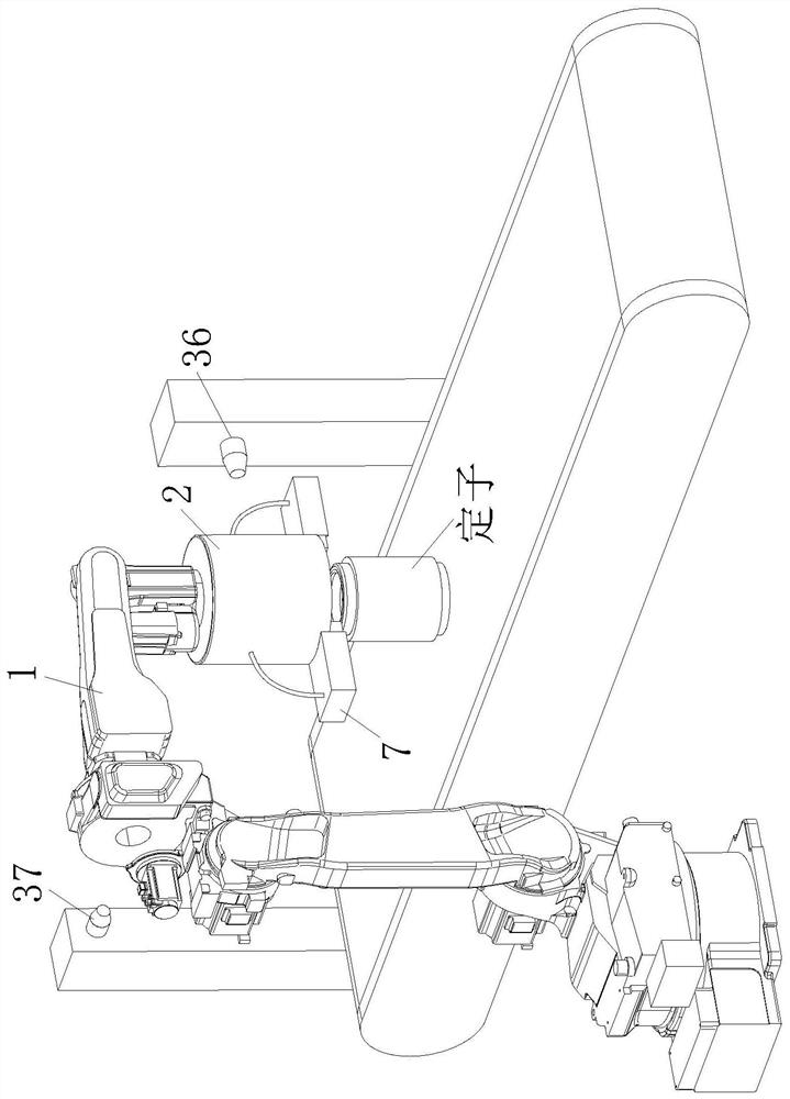
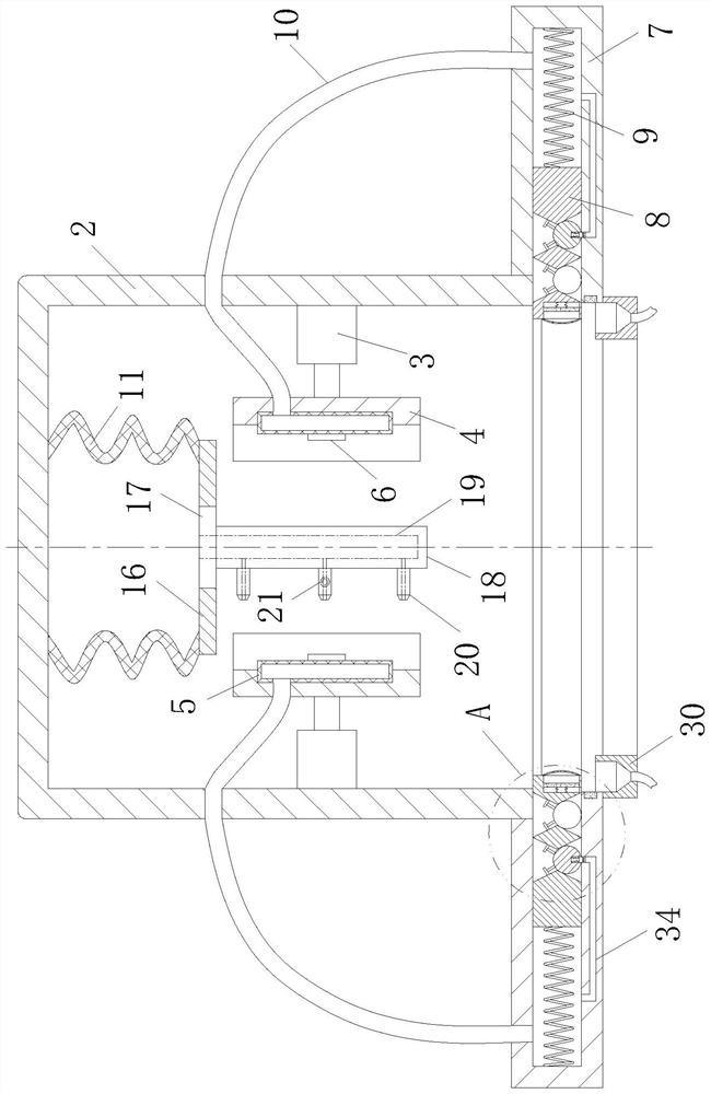
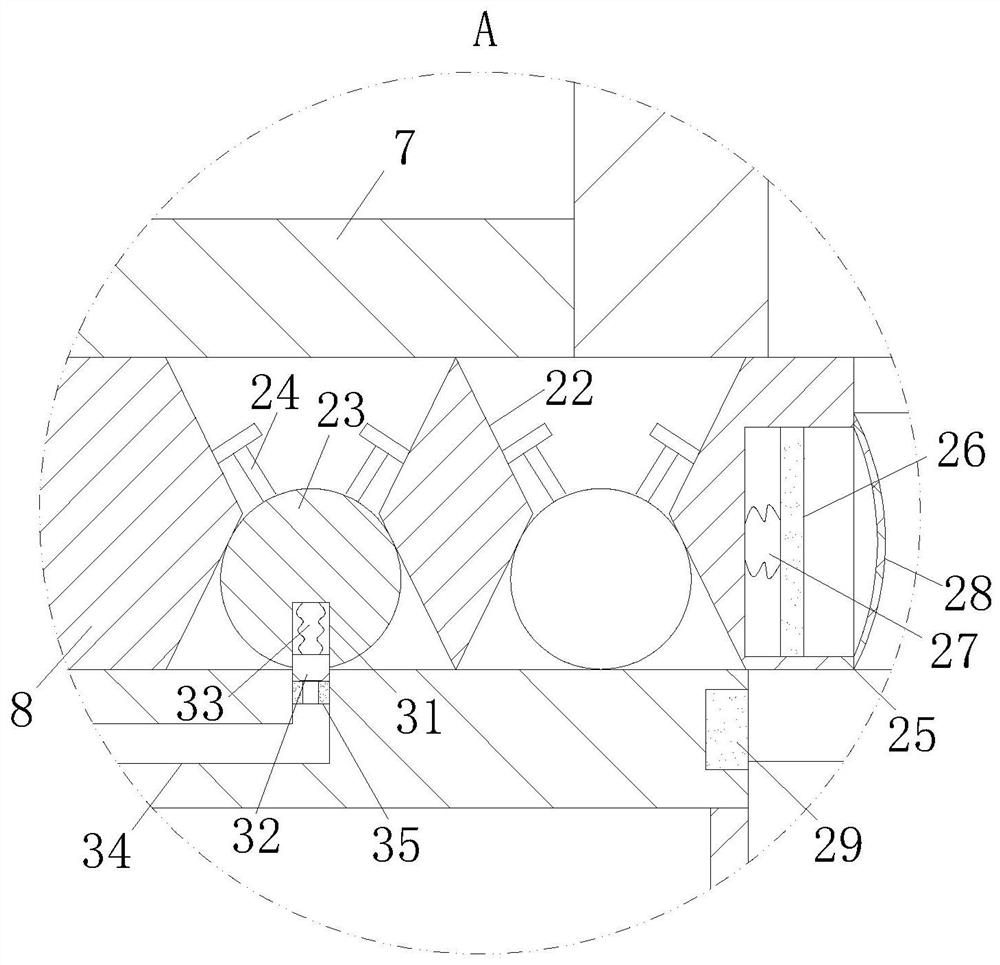
[0029] like Figure 1-Figure 3 As shown, a precise control device for a manipulator according to the present invention includes a manipulator 1; a grasping chamber 2 is provided at the end of the manipulator 1, and a push rod 3 is symmetrically installed inside the grasping chamber 2. The other end of the push rod 3 is connected with an arc-shaped splint 4, the side of the splint 4 close to each other is equipped with an airbag 5, and the symmetrical positions of the two airbags 5 are respectively provided with an inductor 6, and the grasping cavity 2 The bottom end of the sliding cavity 7 is symmetrically connected with a sliding cavity 7, and the inside of the sliding cavity 7 is slidably connected with a baffle plate 8, and a spring 9 is connected between the baffle plate 8 and the inner end of the sliding cavity 7, and the air bag 5 is connected to the corresponding sliding cavity. The inner ends of the cavity 7 are respectively connected through air pipes 10; when working...

Embodiment 2

[0038] like Figure 4 As shown in Comparative Example 1, another embodiment of the air injection assembly is as follows: the air injection assembly also includes a bottom plate 12 positioned at the bottom end of the telescopic bag 11, a connecting rod 13 is provided in the middle of the bottom plate 12, and the bottom plate 12 and The inside of the connecting rod 13 is respectively provided with an air channel 14, and the connecting rod 13 is connected with several sets of shunt tubes 15 communicating with the air channel 14 along its axial direction, and each group of shunt tubes 15 is circularly spaced along the axis of the connecting rod 13. When working, when the flexible bag 11 is compressed under the action of the stator, the gas inside it can be sprayed out from each branch pipe 15 through the air channel 14, so that the enameled coil on the stator can be fully and evenly blown , greatly improving the cleaning effect of the flexible bag 11 on the stator.

[0039] A pre...


PUM


Abstract

The invention relates to the technical field of manipulators, in particular to an accurate control system and control device for a manipulator. A grabbing cavity is formed in the end of a mechanical arm, push rods are symmetrically installed in the grabbing cavity, clamping plates are connected to the other ends of the push rods, air bags are installed on the sides, close to each other, of the clamping plates, sensors are arranged at the symmetrical positions of the two air bags correspondingly, sliding cavities are connected to the bottom end of the grabbing cavity, baffles are slidably connected into the sliding cavities, springs are connected between the baffle and the inner ends of the sliding cavities, and the air bags are connected with the corresponding inner ends of the sliding cavities through air pipes. The situation that a stator falls off between the two clamping plates and is damaged can be reduced, meanwhile, the arranged sensors can facilitate workers to effectively master the working state of the mechanical arm, the movement track of the mechanical arm is adjusted when needed, convenience and rapidness are achieved, and meanwhile the turnover quality of the mechanical arm for the stator is improved.

Description

technical field [0001] The invention relates to the technical field of manipulators, in particular to a precise control system and a control device for a manipulator. Background technique [0002] The types of manipulators can be divided into hydraulic, pneumatic, electric and mechanical manipulators according to the driving mode; they can be divided into special manipulators and general manipulators according to the scope of application; they can be divided into point control and continuous manipulators according to the motion trajectory control mode. Trajectory control manipulators, etc.; manipulators can save workers, improve efficiency, reduce costs, improve product quality, and have good safety; while manipulators are often controlled by control programs, allowing manipulators to operate and control according to preset motion modes, but this control The control accuracy of the method is not high during work, and with the frequent movements of the manipulator, operation ...

Claims


Application Information

Patent Timeline
Patent Type & Authority Applications(China)
IPC IPC(8): B25J9/16B25J13/00B25J15/00B25J15/08B25J19/00
CPCB25J15/00B25J15/08B25J9/161B25J9/1664B25J9/1661B25J13/00B25J19/00Y02P90/02
Inventor 王惠姣方映高庆云
Owner HANGZHOU VOCATIONAL & TECHN COLLEGE
Learn More