
Wafer film coating equipment

A film coating and equipment technology, applied in the field of wafer coating equipment, can solve the problems affecting the uniformity of the coating film on the wafer surface and the uneven placement of the wafer, and achieve the effect of avoiding the uneven placement of the wafer

Inactive Publication Date: 2021-07-23
梁小明
View PDF0 Cites 0 Cited by
  • Summary
  • Abstract
  • Description
  • Claims
  • Application Information

AI Technical Summary

Problems solved by technology

[0004] Aiming at an existing wafer coating equipment, when coating a wafer, since the coating film material is a liquid coating film, the liquid coating film flows on the surface of the wafer, so that the liquid coating film moves toward the surface when the coating film is flattened. The edge of the wafer flows, causing part of the liquid coating film to flow into the wafer support seat and accumulate, resulting in the uneven placement of the wafer and affecting the uniformity of the coating film on the wafer surface. The invention provides a wafer coating equipment to solve the problem. above technical issues

Method used


Image

  • Wafer film coating equipment
  • Wafer film coating equipment
  • Wafer film coating equipment

Examples


Embodiment 1

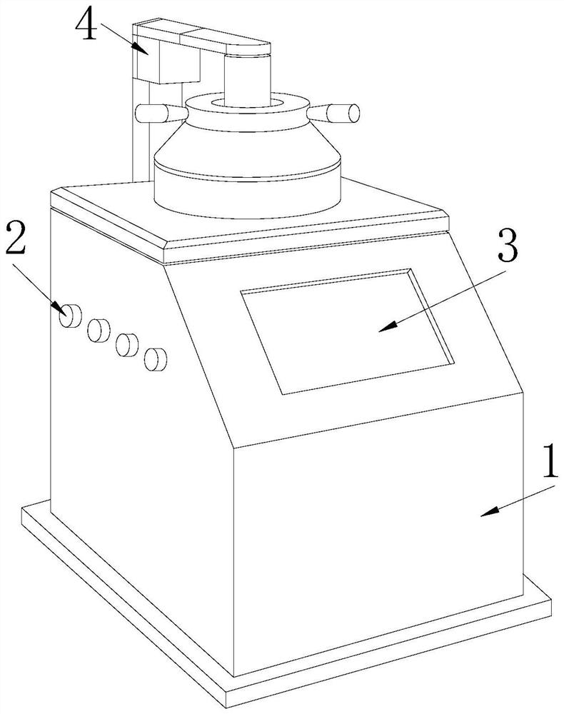
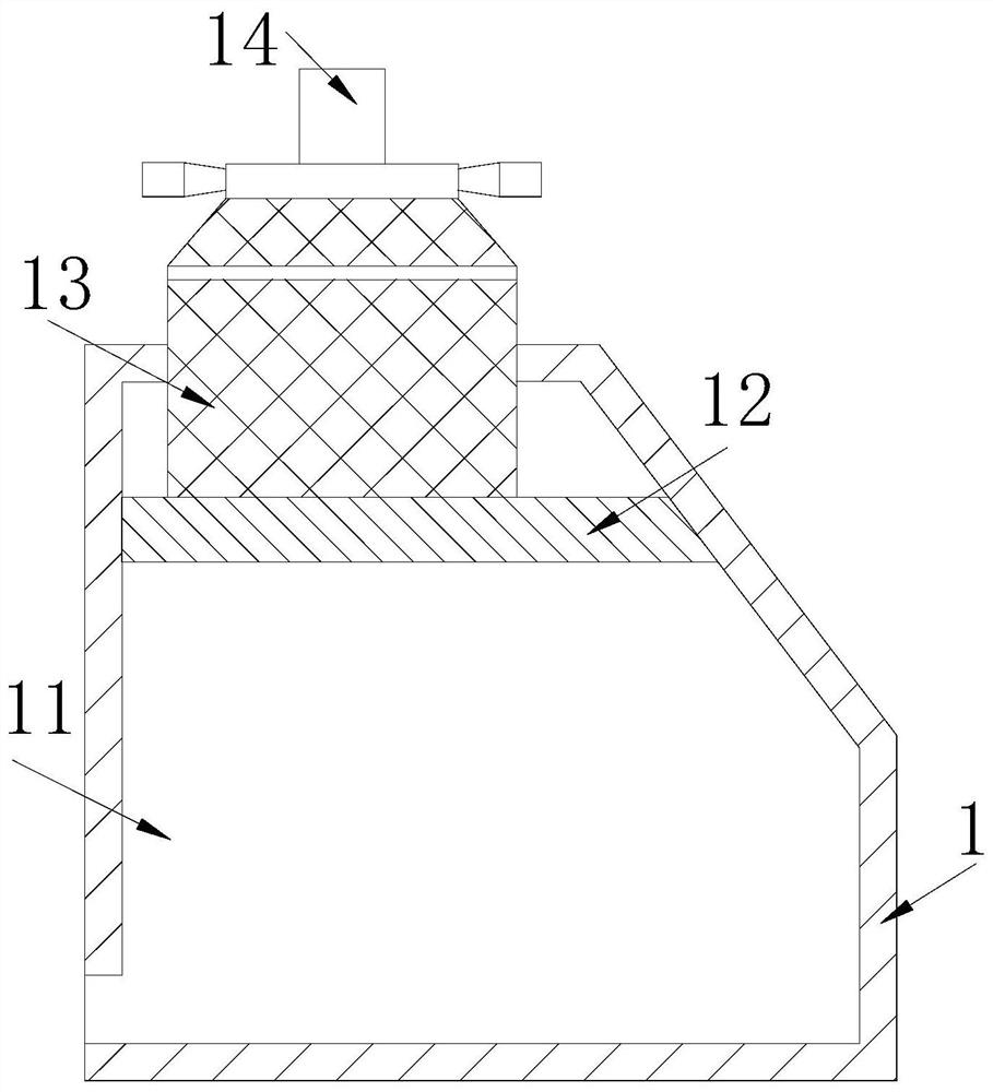
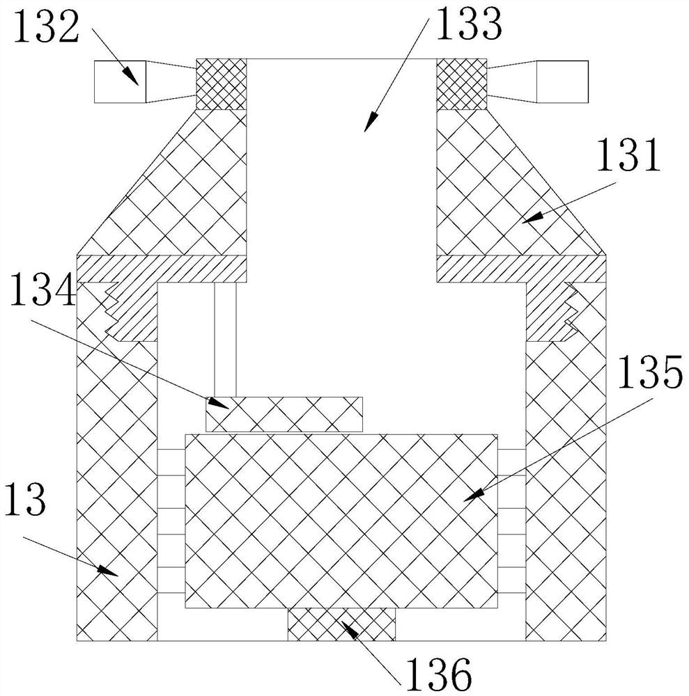
[0029] The present invention provides a wafer coating equipment, the structure of which includes a storage box 1, a button 2, a display 3, and a film feeder 4, the button 2 is installed on the left side of the storage box 1, and the display 3 is embedded in the storage box 1 front side, the two ends of the film feeder 4 are respectively connected to the back of the storage box 1 and the top of the storage box 1 by welding, the storage box 1 includes a storage cavity 11, a fixed plate 12, a film coating box 13, and a through pipe 14, The storage cavity 11 is embedded in the storage box 1, and the storage cavity 11 is connected to one end of the film delivery device 4, the fixed plate 12 is connected to the inner wall of the storage cavity 11 by horizontal welding, and the bottom of the coating box 13 is embedded Fixed on the upper surface of the fixed plate 12, the through pipe 14 is vertically arranged on the top of the film coating box 13, and the top of the through pipe 14 is...

Embodiment 2

[0036] The present invention provides a wafer coating equipment, the structure of which includes a storage box 1, a button 2, a display 3, and a film feeder 4, the button 2 is installed on the left side of the storage box 1, and the display 3 is embedded in the storage box 1 front side, the two ends of the film feeder 4 are respectively connected to the back of the storage box 1 and the top of the storage box 1 by welding, the storage box 1 includes a storage cavity 11, a fixed plate 12, a film coating box 13, and a through pipe 14, The storage cavity 11 is embedded in the storage box 1, and the storage cavity 11 is connected to one end of the film delivery device 4, the fixed plate 12 is connected to the inner wall of the storage cavity 11 by horizontal welding, and the bottom of the coating box 13 is embedded Fixed on the upper surface of the fixed plate 12, the through pipe 14 is vertically arranged on the top of the film coating box 13, and the top of the through pipe 14 is...


PUM


Abstract

The invention discloses wafer film coating equipment which structurally comprises a storage box, buttons, a displayer and a film conveying device. The buttons are installed on the left side of the storage box, the displayer is embedded in the front side of the storage box, and the two ends of the film conveying device are connected to the back face of the storage box and the top of the storage box through welding correspondingly. The wafer film coating equipment has the beneficial effects that a wafer is placed on a supporting block, clamping plates clamp the wafer under the thrust of supporting springs, the wafer is prevented from falling off during film coating, meanwhile, moving rods are extruded by the clamping plates, so that jacking blocks stretch outwards till pressing plates are tightly attached to the surfaces of the clamping plates, and the situation that the clamping plates shake when clamping the wafer, and consequently film coating is uneven is avoided; and the outer surface of the wafer extrudes the clamping plates outwards, wafers of different sizes can be clamped and coated under the tensile force of tension springs, when the liquid film coating on the surface of the wafer is leveled by a scraping plate, the redundant liquid film coating can be discharged into a storage cavity along guide pipes to be stored, and the situation that the wafer is placed unstably due to the fact that the liquid film coating is accumulated in empty grooves is avoided.

Description

technical field [0001] The invention relates to the field of wafer coating, in particular to a wafer coating equipment. Background technique [0002] Wafers are the raw materials for making chips. When making chips, the wafers need to be processed to make the chips meet the standard. During the processing of the wafers, the wafers will be coated with the wafer coating equipment to make the liquid coating film wrap and cover On the surface of the wafer, the oxidation resistance and high temperature resistance of the wafer are greatly improved. [0003] At present, an existing wafer coating equipment, when coating a wafer, because the coating material is a liquid coating film, the liquid coating film flows on the wafer surface, so that when the coating film is flattened, the liquid coating film flows toward the surface of the wafer. The edge of the wafer flows, causing part of the liquid coating film to flow to the wafer support seat to accumulate, resulting in unstable place...

Claims


Application Information

Patent Timeline
Patent Type & Authority Applications(China)
IPC IPC(8): B29C41/20B29C41/34H01L21/67
CPCB29C41/20B29C41/34H01L21/6715
Inventor 梁小明
Owner 梁小明
Learn More