Supercharge Your Innovation With Domain-Expert AI Agents!

Electroplating device suitable for preparing small-area radioactive source

An electroplating device and radioactive source technology, applied in the electrolysis process, electrolysis components, etc., can solve the problems of cathode approach, deviation of the active area of ​​the radioactive source from the center, and difficulty in peeling off.

Inactive Publication Date: 2021-07-23
INST OF NUCLEAR PHYSICS & CHEM CHINA ACADEMY OF
View PDF4 Cites 0 Cited by
  • Summary
  • Abstract
  • Description
  • Claims
  • Application Information

AI Technical Summary

Problems solved by technology

Currently, a vertical electroplating tank structure (such as Image 6 As shown), there are the following defects: 1. It is difficult to keep the alignment of the two dots on the vertical line with the "Π" type base when the plating tank body is installed, which will cause the active area of ​​the radioactive source obtained by electroplating to deviate Center, not centered; 2. Its "0" type gasket is also prone to deviate from the dot, resulting in the area of ​​the electroplated metal substrate exposed to the electroplating solution not in the central area of ​​the substrate; 3. Electroplating according to the tapered design In the inner tank, the size of the anode will limit the adjustment range of the electrode spacing, that is, when the anode area is large, it cannot be well approached to the cathode below. In other words, when it is necessary to carry out research on the influence of the electrode spacing on the electroplating effect, The minimum distance between electrodes can only be equal to the diameter of the anode; 4. After the electroplating is completed, the metal backing is often subjected to a large vertical pressure, making it close to the "Π"-shaped base, which is difficult to peel off

Method used


Image

  • Electroplating device suitable for preparing small-area radioactive source
  • Electroplating device suitable for preparing small-area radioactive source
  • Electroplating device suitable for preparing small-area radioactive source

Examples


Embodiment Construction

[0021] The present invention will be further explained in detail below in conjunction with the accompanying drawings.

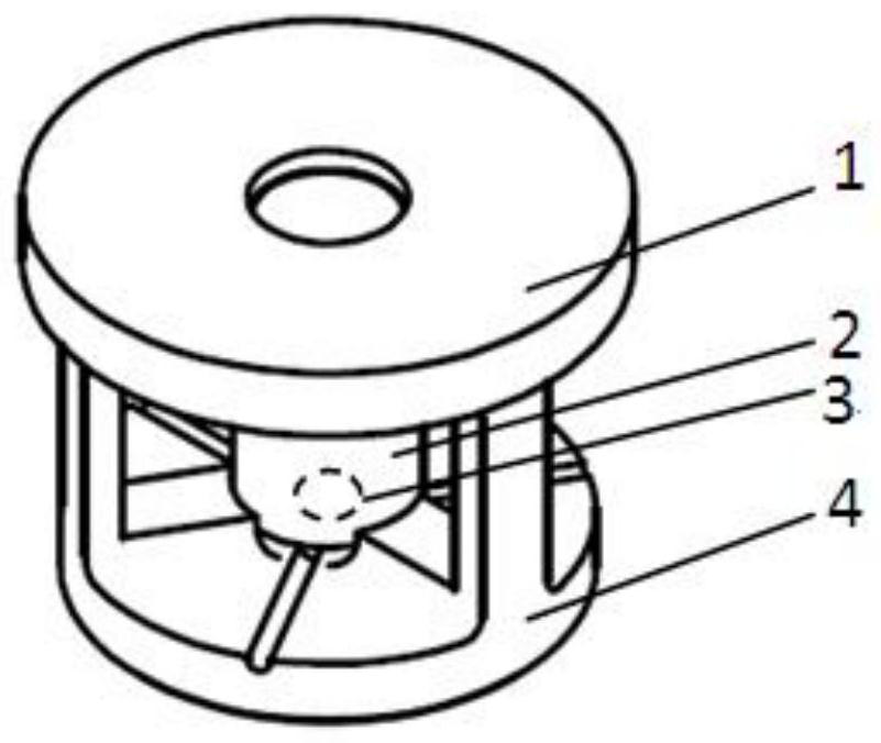
[0022] Such as Figure 1 to Figure 5 As shown, the electroplating device suitable for the preparation of small-area radioactive sources in the present invention includes a cover 1, a tank body 2, a gasket 3 and an electroplating tank base 4. During assembly, the gasket and the tank body are placed on the electroplating tank base in sequence, and then the cover 1 is connected with the base 4 of the electroplating tank through threads.

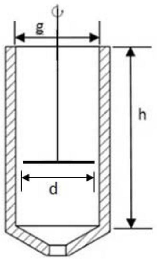
[0023] Described tank body 2 adopts the vertical cavity structure that the bottom gradually narrows, as image 3 As shown, the tank body 2 includes a cylindrical cavity at the upper end and a conical cavity at the lower end, so that the anode can adjust the pole spacing at any height in the cylindrical cavity area, that is, when the diameter d of the anode is slightly smaller than the diameter g of the inner cavity of the tank...


PUM


Abstract

The invention discloses an electroplating device suitable for preparing a small-area radioactive source. The electroplating device comprises a cover, a tank body, a gasket and an electroplating tank base; the tank body adopts a vertical cavity structure with a gradually narrowed bottom, the tank body comprises an upper-end cylindrical cavity and a lower-end conical cavity, and the tank body is fixed to the electroplating tank base; the electroplating tank base is of an I-shaped cavity structure, the upper end of the electroplating tank base is connected with the cover, and the lower end of the electroplating tank base is provided with a groove located in the center and a plurality of guide grooves evenly distributed in the circumferential direction of the groove; the groove is used for placing the gasket and a metal substrate serving as a cathode; and the cover is of a hollow structure. By utilizing the electroplating device, the electroplating tank body and an electroplating metal bottom lining can be centered in a glove box or a working box through simple operation while small-area radioactive source electroplating is realized, the metal bottom lining can be conveniently taken out after electroplating, and an inter-electrode distance adjusting process experiment can be conveniently carried out.

Description

technical field [0001] The invention belongs to the technical field of radioactive source preparation, and in particular relates to an electroplating device suitable for small-area radioactive source preparation. Background technique [0002] With the rapid development of radioactive sources in the field of nuclear technology applications and their in-depth application in the field of nuclear science research, people are paying more and more attention to the preparation quality and technology of radioactive sources. Electroplating, as the most commonly used method for preparing radioactive sources, has the advantages of high electrodeposition efficiency, less demand for raw materials, simple operation, less equipment required, and easy access to conditions, and is especially suitable for some rare and expensive actinide nuclides. Radioactive source preparation. For small-area actinide radioactive sources, the quality of the radioactive source is greatly affected by the elec...

Claims


Application Information

Patent Timeline
Patent Type & Authority Applications(China)
IPC IPC(8): C25D17/00C25D17/08C25D7/00
CPCC25D17/00C25D17/08C25D7/00
Inventor 邓建何遥胡睿李刚郭继军涂俊陈琪萍林青川陈铭
Owner INST OF NUCLEAR PHYSICS & CHEM CHINA ACADEMY OF
Features
  • R&D
  • Intellectual Property
  • Life Sciences
  • Materials
  • Tech Scout
  • Unparalleled Data Quality
  • Higher Quality Content
  • 60% Fewer Hallucinations
Learn More