
Electrostatic spinning device

An electrospinning and wire electrode technology, which is applied in textiles and papermaking, filament/thread forming, fiber processing, etc., can solve the problems of troublesome cleaning of the liquid coating device, low efficiency of the moving mechanism, and low spinning efficiency, etc., to achieve The reciprocating motion process is stable, the spinning efficiency is high, and the liquid supply is convenient.

Pending Publication Date: 2021-07-23
青岛中科凯尔科技有限公司
View PDF0 Cites 0 Cited by
  • Summary
  • Abstract
  • Description
  • Claims
  • Application Information

AI Technical Summary

Problems solved by technology

However, spinning with a wire-electrode liquid-coating electrospinning device has disadvantages such as low spinning efficiency, uneven coating liquid, troublesome cleaning of the liquid coating device, and low efficiency of the movement mechanism.

Method used


Image

  • Electrostatic spinning device
  • Electrostatic spinning device
  • Electrostatic spinning device

Examples


Embodiment 1

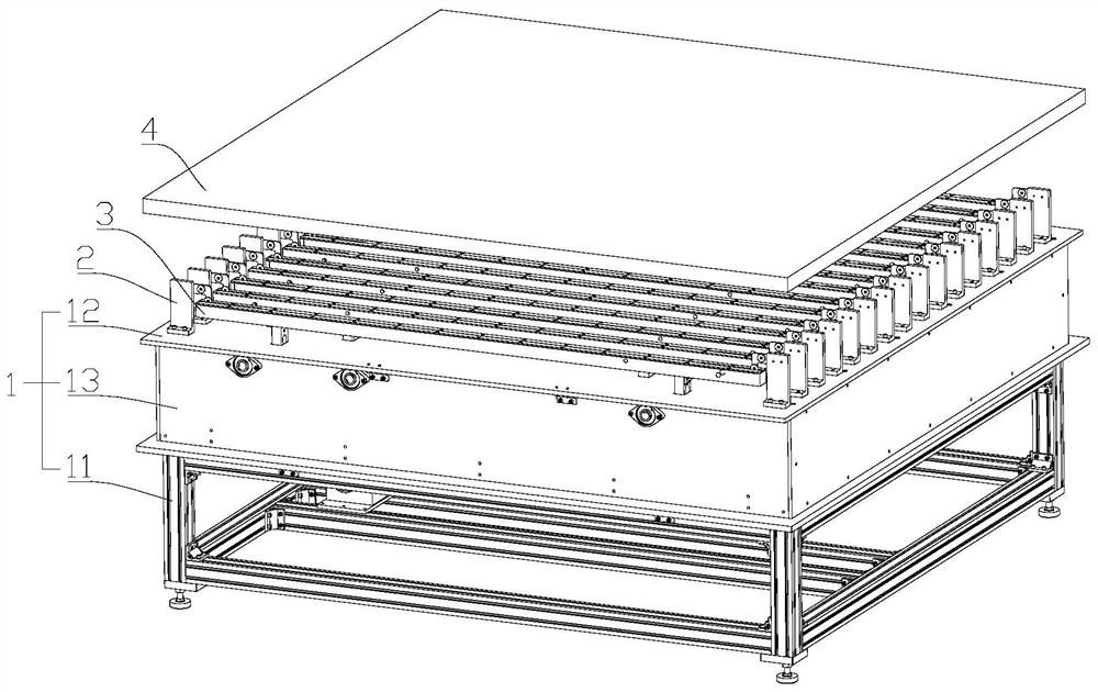
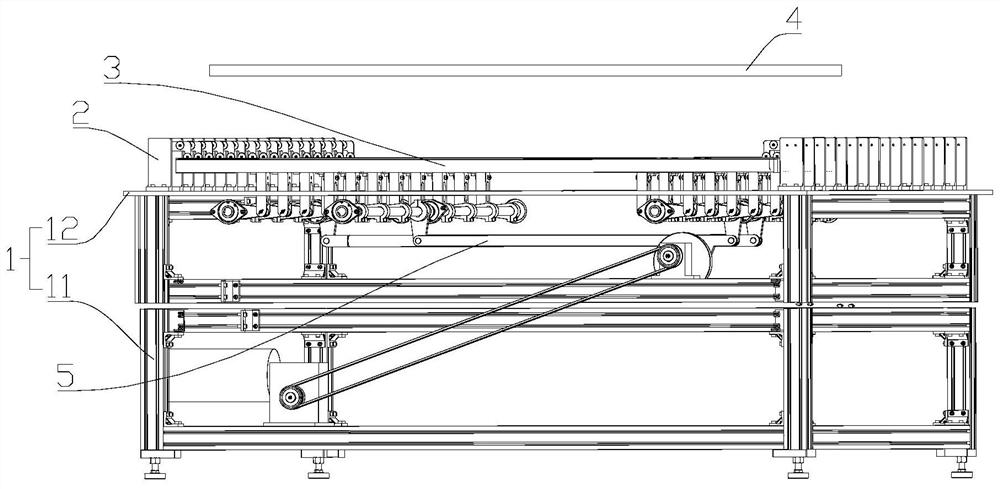
[0033] Such as Figure 1-Figure 8 As shown, the present embodiment relates to an electrospinning device, including a frame 1, on which a plurality of wire electrodes 6 extending in the transverse direction are fixed, and the plurality of wire electrodes 6 are arranged in rows along the longitudinal direction, and each wire electrode 6 are all connected to a positive high-voltage power supply 7, and a receiving terminal 4 is arranged above the plurality of wire electrodes 6, and the receiving terminal 4 is connected to a negative high-voltage power supply 8 (it should be noted that the receiving terminal 4 can also be grounded); the bottom of each wire electrode 6 They are all correspondingly equipped with a liquid tank 3 filled with spinning solution. The liquid tank 3 and the wire electrode 6 have the same extension direction and arrangement. The liquid tank 3 can reciprocate up and down relative to the wire electrode 6, so that the wire electrode 6 is immersed Switch back an...

Embodiment 2

[0043] The difference between this embodiment and Embodiment 1 is that: Figure 10 As shown, in this embodiment, the first liquid tank 31 and the second liquid tank 32 are arranged in such a way that two second liquid tanks 32 are provided every two first liquid tanks 31; correspondingly, as Figure 11 As shown, the arrangement of the first transmission assembly 504 and the third transmission assembly 506 on the first rotating shaft 501 is that two third transmission assemblies 506 are provided every two first transmission assemblies 504, and every two third transmission assemblies 506 on the second rotating shaft 502 Each second transmission assembly 505 and every two fourth transmission assemblies 507 on the third rotating shaft 503 are arranged alternately.

[0044] It can be understood that the embodiment of the present invention is not limited to the arrangement of the first liquid tank 31 and the second liquid tank 32 adopted in the first and second embodiments, and thos...


PUM


Abstract

The invention provides an electrostatic spinning device, and belongs to the technical field of electrostatic spinning. The device can realize continuous batch spinning, and is high in spinning efficiency, uniform in spinning, convenient in liquid supply and convenient to clean. The electrostatic spinning device comprises a rack; a plurality of line electrodes extending in the transverse direction are fixed to the rack; the multiple line electrodes are arranged in rows in the longitudinal direction; a receiving end is arranged above the multiple line electrodes; a liquid tank containing a spinning solution is correspondingly arranged below each line electrode; the liquid tanks and the line electrodes have the same extension direction and arrangement mode; the liquid tanks can reciprocate up and down relative to the line electrodes, so that the line electrodes can be switched between a dipping state in which the line electrodes are immersed in the spinning solution and a spinning state in which the line electrodes are separated from the spinning solution in a reciprocating mode; the liquid tanks are divided into two groups, namely a first liquid tank and a second liquid tank; the rack is provided with a driving mechanism used for driving the first liquid tank and the second liquid tank to reciprocate in the opposite directions; and the driving mechanism is connected to the first liquid tank and the second liquid tank.

Description

technical field [0001] The invention belongs to the technical field of electrostatic spinning, and in particular relates to an electrostatic spinning device. Background technique [0002] At present, the forms of high-voltage electrospinning mainly include needle type, wire electrode coating type and so on. The spinning process using a needle-type electrospinning device is as follows: the solution passes through a needle with positive high voltage under the assistance of a propulsion pump, etc., the receiving end is grounded or connected to a negative high voltage, and the solution forms a Taylor cone at the tip of the needle under the action of an electric field , and extend from the conical tip to obtain fiber filaments. However, the use of a needle-type electrospinning device for spinning has disadvantages such as low spinning efficiency, troublesome installation / cleaning of the needle, easy blockage of the needle, and easy dripping during spinning. The process of spinn...

Claims


Application Information

Patent Timeline
Patent Type & Authority Applications(China)
IPC IPC(8): D01D5/00
CPCD01D5/0061
Inventor 于淼龙云泽
Owner 青岛中科凯尔科技有限公司
Learn More