Self-tie steel-wood combined joint and mounting method

A technology of steel-wood combination and joints, which is applied in the direction of architecture and building construction, can solve problems such as no recovery ability, small parts are easy to break, and complex connections, so as to avoid large deformation and damage, improve integrity and energy consumption capacity , Improve the effect of the overall mechanical properties

Active Publication Date: 2021-07-23
QINGDAO TECHNOLOGICAL UNIVERSITY
View PDF10 Cites 2 Cited by
  • Summary
  • Abstract
  • Description
  • Claims
  • Application Information

AI Technical Summary

Problems solved by technology

[0003] However, the connection nodes of existing wooden structures have many components and complex connections, and the cross-section of the column is usually pierced due to the need for connection, which is likely to cause stress concentration; Dissipation of earthquake energy leads to problems such as single material used, small parts are easy to break, no recovery ability, and the mechanical properties of wood cannot be maximized in earthquakes.

Method used


Image

  • Self-tie steel-wood combined joint and mounting method
  • Self-tie steel-wood combined joint and mounting method
  • Self-tie steel-wood combined joint and mounting method

Examples


Embodiment 1

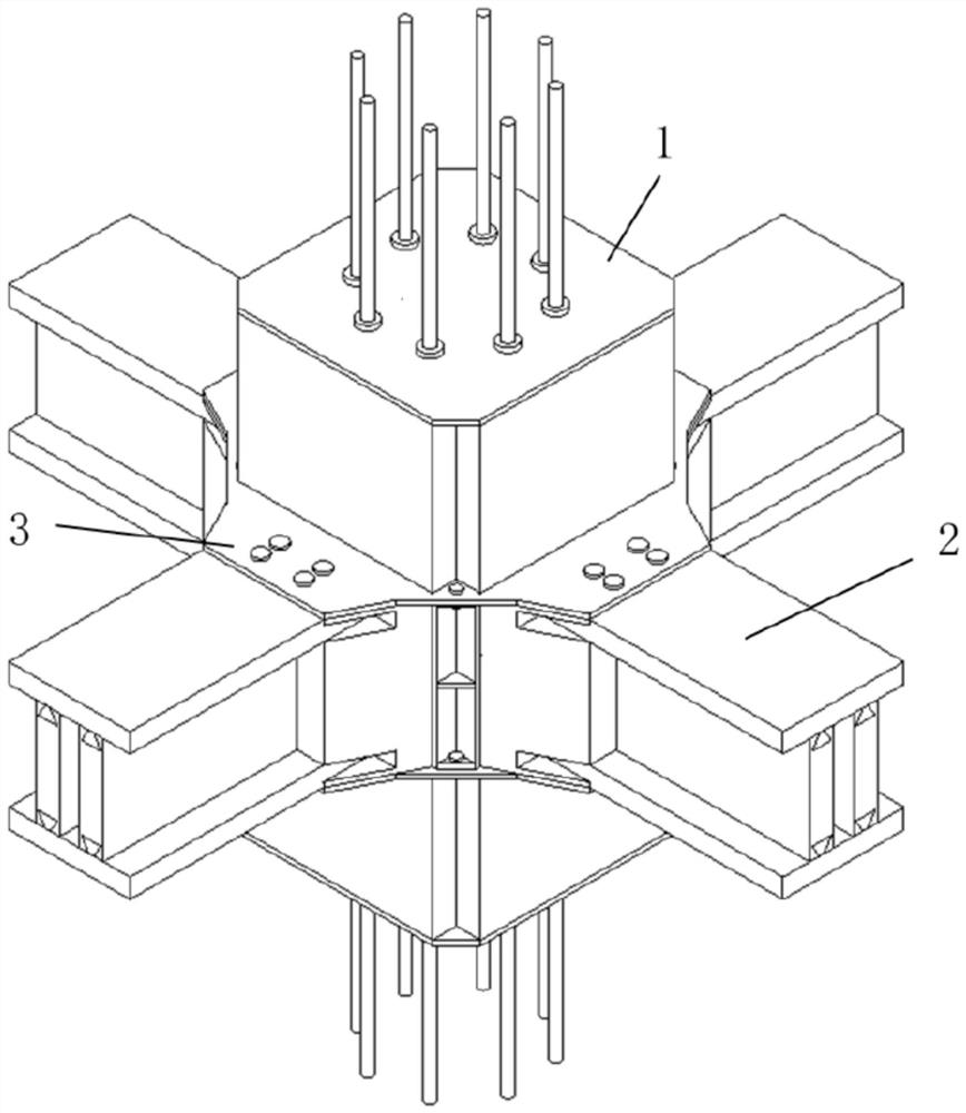
[0052] Such as figure 1 As shown, the self-tensioning steel-wood composite node of this embodiment includes a self-tensioning composite column 1 , a composite beam 2 and a beam-column reinforcement kit 3 .

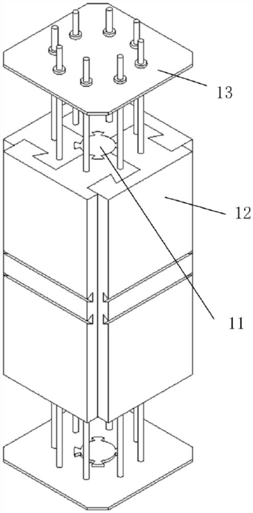
[0053] Such as figure 2 As shown, the self-tie composite column includes a central column 11 and four peripheral tie columns 12 located outside the central column 11. The two adjacent peripheral tie columns are connected by mortise and tenon, and the central column and its outer periphery The mortise and tenon connection of the pull knot column forms a square column.

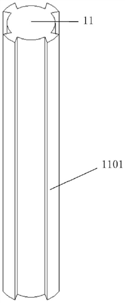
[0054] Such as image 3 As shown, four dovetail-shaped tenons 1101 are evenly distributed on the central column 11 along the circumference of the column, and the dovetail-shaped tenons 1101 are integrated with the central column 11 and have the same height.

[0055] Such as Figure 4 to Figure 6As shown, the cross-section of the peripheral tie column 12 is L-shaped, including the horizontal short side 1...

Embodiment 2

[0068] The difference between this embodiment and Embodiment 1 is that the composite beam and the self-tensioning composite column are connected through the beam-column connection block 4, such as Figure 12 As shown, a horizontal tenon 41 is provided on one side of the beam-column connection block 4 , horizontal sockets 42 are provided at the upper and lower ends of the corresponding other side, and vertical tenons 43 are provided between the horizontal sockets.

[0069] In this embodiment, since the composite beam 2 is connected with the beam-column connecting block 4, the structure of the composite beam 2 is also changed, as Figure 13 As shown, there is a vertical mortise 2202 at the front end of the web, and the mortise on the inner side of the flange plate and the mortise 2201 on the top and bottom of the web do not run through the entire length, but are short.

[0070] When connecting, first insert the horizontal mortise 41 of the beam-column connecting block 4 into the...


PUM


Abstract

The invention relates to the field of building structures, and discloses a self-tie steel-wood combined joint and a mounting method. The self-tie steel-wood combined joint comprises a self-tie combined column, combined beams and beam column reinforcing kits. The self-tying combined column comprises a central column body and peripheral tie columns located on the outer side of the central column body, and the central column body and the peripheral tie columns are in mortise and tenon connection to form a square column body. Flange plates of the combined beams are in mortise and tenon connection with webs; The flange plates are in mortise and tenon connection with the peripheral tie columns. Each beam column reinforcing kit comprises two column outer ring plates, and the column outer ring plates are arranged on the self-tie combination column in a sleeving mode and connected with the flange plates through bolts. According to the self-tie combined column, every two surrounding tie columns are tied, the central tie column and the surrounding tie columns are tied mutually, and the integrity and the energy dissipation capacity of members are improved; The energy consumption form of the self-tie combined column is mainly mutual staggered friction of different parts of the self-tie combined column in the vertical direction, and the phenomenon that a single member is damaged can be avoided.

Description

technical field [0001] The invention relates to the field of building structures, in particular to a self-tensioning steel-wood composite node and an installation method. Background technique [0002] Timber structure buildings use wood as the force-bearing member, which has better tensile capacity than concrete materials, is not easy to be brittle, and does not require curing time. As the main material of construction, wood is environmentally friendly, and compared with reinforced concrete buildings and steel structure buildings, it reduces a large amount of carbon emissions. At the same time, the connection characteristics and material characteristics of wooden structure buildings determine its faster construction speed. [0003] However, the connection nodes of existing wooden structures have many components and complex connections, and the cross-section of the column is usually pierced due to the need for connection, which is likely to cause stress concentration; Dissi...

Claims


Application Information

Patent Timeline
Patent Type & Authority Applications(China)
IPC IPC(8): E04B1/19E04B1/58
CPCE04B1/1912E04B1/1903E04B1/58E04B2001/1915
Inventor 牟犇刘旭
Owner QINGDAO TECHNOLOGICAL UNIVERSITY
Why Eureka
Try Eureka