Caulk filling machine for indoor decoration

A technology of beautifying joint agent and interior decoration, which is applied in the direction of construction and building construction, which can solve the problems of labor-intensive, low efficiency, and difficulty in ensuring the uniformity of knocking, etc., to improve construction quality, eliminate gaps, and improve filling efficiency Effect

Active Publication Date: 2021-07-23
WUXI CITY COLLEGE OF VOCATIONAL TECH
View PDF8 Cites 0 Cited by
  • Summary
  • Abstract
  • Description
  • Claims
  • Application Information

AI Technical Summary

Problems solved by technology

Although the construction method of filling and applying the joint beautifying agent twice after hitting with a rubber hammer can greatly improve the quality of the beautifying joint filling and meet the requirements of high-end decoration, but it often requires the cooperation of two people, which is not only low

Method used


Image

  • Caulk filling machine for indoor decoration
  • Caulk filling machine for indoor decoration
  • Caulk filling machine for indoor decoration

Examples


Embodiment 1

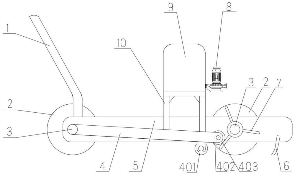
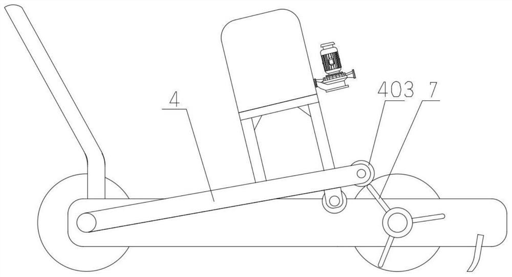
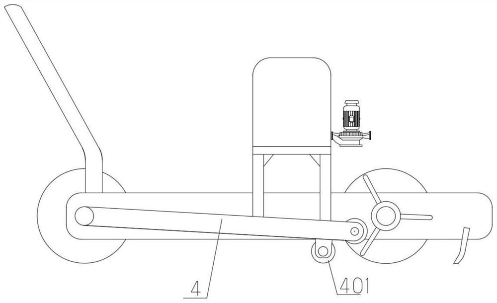
[0033] combine figure 1 and Figure 4 As shown, the two traveling wheels 2 on both sides in front of the cart 5 are connected to the same wheel shaft 3, and three driving levers 7 for cooperating with the swing rods 4 on the corresponding sides are respectively provided at the two ends of the wheel shaft 3. Any driving rod 7 is distributed along the radial direction of the wheel shaft 3, and the three swing rods 4 located at the same end of the wheel shaft 3 are evenly spaced along the circumference of the wheel shaft 3, and the three swing rods 4 at one end of the wheel shaft 3 and the three swing rods 4 at one end of the wheel shaft 3 The projections of the three swing rods 4 at the other end on the axial direction of the wheel shaft 3 overlap one by one. The three driving rods 7 are evenly spaced, so that the driving wheel 2 rotates once to drive the striking mechanism to trigger three times, which improves the striking frequency of the striking part 401, and is beneficial...

Embodiment 2

[0038] combine Figure 5 and Figure 9 As shown, in this embodiment, three driving rods 7 are also respectively provided at the two ends of the wheel shaft 3 in front of the cart 5 , and the driving rods 7 are also fixed on the sleeve 12 slidably arranged on the wheel shaft 3 . Different from Embodiment 1, the projections of the three levers 7 at one end of the wheel shaft 3 and the three levers 7 at the other end of the wheel shaft 3 in the axial direction of the wheel shaft 3 are distributed alternately in this embodiment. Through such a distribution mode of the driving rod 7, the balance pendulum 4 is fed back to the retarding effect of the reaction force produced by the traveling wheel 2 when the driving rod 7 is moved upwards, and the traveling wheels 2 on both sides are reduced or avoided during the progress of the cart 5. The stagnation or movement caused by the synchronous blocking effect ensures the uniformity of the beautifying agent filling. in such as Figure 9 ...

Embodiment 3

[0043] The technical solution of this embodiment is the same as the main body of Embodiment 2. Three driving levers 7 are respectively arranged on both sides of the front of the cart 5, and the driving levers 7 at both ends of the wheel shaft 3 are respectively staggered; The injection pump 8 selectively loads its own gravity on the swing rod 4 on the falling side to increase the striking force of the striking member 401 . The difference is that this embodiment provides another setting method of the cosmetic agent tank 9 and the injection pump 8, specifically:

[0044] Such as Figure 10 As shown: the upper sides of the two swing rods 4 close to the matching portion 402 are respectively provided with vertically distributed ejector rods 15 . The lower ends of the two push rods 15 are respectively welded and fixed on the corresponding swing rods 4, the upper ends of the push rods 15 are inserted through the two ends of the length direction of the same swing table 18, and the pu...


PUM


Abstract

The invention discloses a caulk filling machine for indoor decoration. The caulk filling machine for indoor decoration is provided with a cart; advancing wheels, a caulk tank and a filler nozzle are arranged on the cart; the caulk filling machine further comprises a beating mechanism arranged on the cart and located behind the filler nozzle; the beating mechanism is used for beating ceramic tiles in the advancing process of the cart to vibrate the ceramic tiles; the beating mechanism comprises two swing rods arranged on the two sides of the cart respectively and shifting rods used for shifting the corresponding swing rods to swing; one end of each swing rod is rotationally arranged on the cart; a matching part allowing the shifting rods to shift upwards is formed at the other end of each swing rod; beating pieces are arranged on the lower sides, close to the matching parts, of the swing rods; the beating pieces are used for falling under the action of gravity to beat the ceramic tiles after the shifting rods shift the matching parts of the swing rods to rotate upwards and are separated from the matching parts; and the shifting rods are fixed on a wheel shaft of the corresponding advancing wheel close to the corresponding matching part and synchronously rotate along with the corresponding advancing wheel. According to the invention, the caulk filling speed can be increased, and the caulk after filling can be denser and more uniform.

Description

technical field [0001] The invention relates to the field of interior decoration construction equipment, in particular to a beautifying joint filling machine for interior decoration. Background technique [0002] In the laying of ceramic tile floors for interior decoration, more and more people choose to fill the gaps of tiles with beautifying agent. It enriches the color and composition of the floor to meet people's increasing aesthetic needs. [0003] The seam beautification agent in the prior art is usually filled by manual tools such as glue guns, or by using a trolley-type beautifying machine to fill while moving. The agent is pushed inward from the top of the tile gap into the gap, so it is easy to cause uneven filling and gaps during the pushing process of the beautifying agent, which will affect the service life of the beautifying agent, and it is difficult to guarantee its protective effect after long-term use. In order to avoid the gap phenomenon of the beautifyi...

Claims


Application Information

Patent Timeline
IPC IPC(8): E04F21/165
CPCE04F21/165
Inventor 王云菲李继明蔡小玲胡媛媛
Owner WUXI CITY COLLEGE OF VOCATIONAL TECH
Why Eureka
Try Eureka