A beautifying joint filling machine for interior decoration
A technology of beautifying joint agent and interior decoration, which is applied in the direction of construction and building construction, which can solve the problems of labor-intensive, low efficiency, and difficulty in ensuring the uniformity of knocking, etc., to improve construction quality, eliminate gaps, and improve filling efficiency Effect
- Summary
- Abstract
- Description
- Claims
- Application Information
AI Technical Summary
Problems solved by technology
Method used
Image
Examples
Embodiment 1
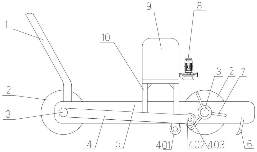
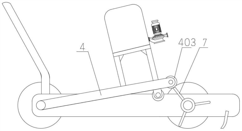
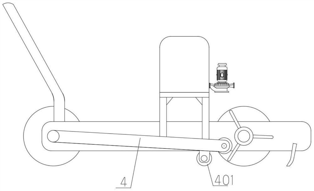
[0033] combine figure 1 and Figure 4 As shown, the two traveling wheels 2 on both sides in front of the cart 5 are connected to the same wheel shaft 3, and three driving levers 7 for cooperating with the swing rods 4 on the corresponding sides are respectively provided at the two ends of the wheel shaft 3. Any driving rod 7 is distributed along the radial direction of the wheel shaft 3, and the three swing rods 4 located at the same end of the wheel shaft 3 are evenly spaced along the circumference of the wheel shaft 3, and the three swing rods 4 at one end of the wheel shaft 3 and the three swing rods 4 at one end of the wheel shaft 3 The projections of the three swing rods 4 at the other end on the axial direction of the wheel shaft 3 overlap one by one. The three driving rods 7 are evenly spaced, so that the driving wheel 2 rotates once to drive the striking mechanism to trigger three times, which improves the striking frequency of the striking part 401, and is beneficial...
Embodiment 2
[0038] combine Figure 5 and Figure 9 As shown, in this embodiment, three driving rods 7 are also respectively provided at the two ends of the wheel shaft 3 in front of the cart 5 , and the driving rods 7 are also fixed on the sleeve 12 slidably arranged on the wheel shaft 3 . Different from Embodiment 1, the projections of the three levers 7 at one end of the wheel shaft 3 and the three levers 7 at the other end of the wheel shaft 3 in the axial direction of the wheel shaft 3 are distributed alternately in this embodiment. Through such a distribution mode of the driving rod 7, the balance pendulum 4 is fed back to the retarding effect of the reaction force produced by the traveling wheel 2 when the driving rod 7 is moved upwards, and the traveling wheels 2 on both sides are reduced or avoided during the progress of the cart 5. The stagnation or movement caused by the synchronous blocking effect ensures the uniformity of the beautifying agent filling. in such as Figure 9 ...
Embodiment 3
[0043] The technical solution of this embodiment is the same as the main body of Embodiment 2. Three driving levers 7 are respectively arranged on both sides of the front of the cart 5, and the driving levers 7 at both ends of the wheel shaft 3 are respectively staggered; The injection pump 8 selectively loads its own gravity on the swing rod 4 on the falling side to increase the striking force of the striking member 401 . The difference is that this embodiment provides another setting method of the cosmetic agent tank 9 and the injection pump 8, specifically:
[0044] Such as Figure 10 As shown: the upper sides of the two swing rods 4 close to the matching portion 402 are respectively provided with vertically distributed ejector rods 15 . The lower ends of the two push rods 15 are respectively welded and fixed on the corresponding swing rods 4, the upper ends of the push rods 15 are inserted through the two ends of the length direction of the same swing table 18, and the pu...
PUM
 Abstract
Description
Claims
Application Information
 - R&D
- Intellectual Property
- Life Sciences
- Materials
- Tech Scout
- Unparalleled Data Quality
- Higher Quality Content
- 60% Fewer Hallucinations
Browse by: Latest US Patents, China's latest patents, Technical Efficacy Thesaurus, Application Domain, Technology Topic, Popular Technical Reports.
© 2025 PatSnap. All rights reserved.Legal|Privacy policy|Modern Slavery Act Transparency Statement|Sitemap|About US| Contact US: help@patsnap.com


