
Lock hook with simple structure and high reliability

A simple and reliable technology, applied in the field of lock hooks, can solve the problems of complex structure, large lock hook device, time-consuming and labor-intensive assembly, etc., achieving a simple and compact structure, high degree of automation, and solving the problem of time-consuming and labor-intensive assembly. Effect

Pending Publication Date: 2021-07-23
DONGGUAN HYXION METAL TECH CO LTD
View PDF0 Cites 0 Cited by
  • Summary
  • Abstract
  • Description
  • Claims
  • Application Information

AI Technical Summary

Problems solved by technology

[0003] The purpose of the present invention is to overcome the above-mentioned defects in the prior art, and provide a lock hook with a simple structure and high reliability, which solves the problem that the lock hook device in the prior art has a large volume and a complex structure, and the assembly is time-consuming and labor-intensive. technical problem

Method used


Image

  • Lock hook with simple structure and high reliability
  • Lock hook with simple structure and high reliability
  • Lock hook with simple structure and high reliability

Examples


Embodiment 1

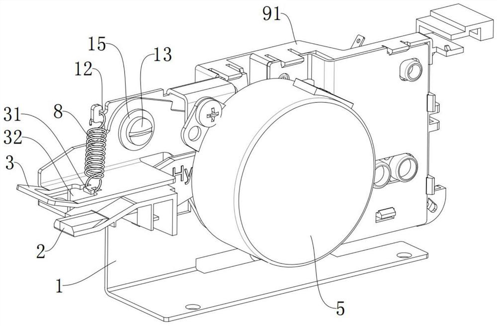
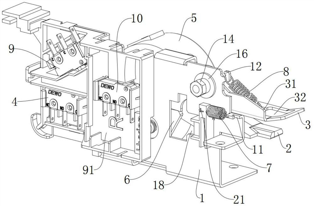
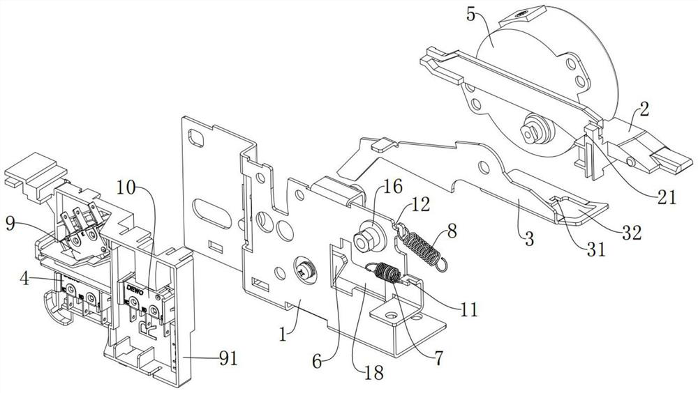
[0021] Please refer to Figure 1-Figure 3 , the present embodiment provides a lock hook with simple structure and high reliability, which includes a lock hook base 1, a lock hook induction plate 2 arranged on the lock hook base 1 for sliding connection, and a lock whose middle part is hinged to the lock hook base 1. The hook piece 3, the first sensor 4, the motor 5, the induction plate extension spring 7, the hook extension spring 8 respectively arranged on the hook seat 1, and the cam 6 which is arranged on the hook seat 1 and connected with the motor 5 in transmission ; One end of the induction plate extension spring 7 is relatively fixed with the lock hook seat 1 and its other end is relatively fixed with the lock hook induction sheet 2; one end of the lock hook extension spring 8 is relatively fixed with the lock hook seat 1 and its other end Relatively fixed with the lock hook sheet 3, the first sensor 4 is used to detect whether the distance that the lock hook induction ...

Embodiment 2

[0029] Please refer to Figure 1-Figure 3 , the present embodiment also provides another lock hook with simple structure and high reliability, which also includes a second sensor 9 and a third sensor 10 respectively relatively fixed on the lock hook seat 1, and the rest of the structure is the same as that of the first embodiment, No longer repeat.

[0030]Specifically, the second sensor 9 is used to detect whether the lock hook plate 3 is locked and locked in place after the cam 6 is driven to move around the axis, and the third sensor 10 is used to detect whether the lock hook plate 3 is pulled by the lock hook extension spring 8 Return to the position where the door can be opened. Specifically, when the lock hook piece 3 is driven by the cam 6 to move around the axis, it will be able to clamp and lock the external lock block. At this time, the second sensor 9 will sense the lock hook piece 3 and transmit a signal to the system. , the system can ensure that the locking act...


PUM


Abstract

The invention discloses a lock hook with a simple structure and high reliability, and relates to the field of lock hooks. The lock hook comprises a lock hook seat, a lock hook induction sheet arranged on the lock hook seat and connected with the lock hook seat in a sliding manner, a lock hook sheet of which the middle part is hinged to the lock hook seat, and a first sensor, a motor, an induction sheet tension spring and a lock hook tension spring which are respectively arranged on the lock hook seat, and a cam arranged on the lock hook seat to rotate and in transmission connection with the motor; one end of the induction sheet tension spring is relatively fixed with the lock hook seat, and the other end of the induction sheet tension spring is relatively fixed with the lock hook induction sheet; one end of the lock hook tension spring is relatively fixed with the lock hook seat, the other end of the lock hook tension spring is relatively fixed with the lock hook sheet, the first sensor is used for detecting whether the sliding distance of the lock hook induction sheet on the lock hook seat is in place or not, and the first sensor is in signal connection with the motor; and the cam drives the lock hook sheet to do axial motion on the lock hook seat. The lock hook solves the technical problems that in the prior art, a lock hook device is large in size and complex in structure, and time and labor are consumed in assembly.

Description

technical field [0001] The invention relates to the technical field of lock hooks, in particular to a lock hook with simple structure and high reliability. Background technique [0002] The lock hook device in the prior art is generally installed in the middle and upper position of the oven door, occupying a certain space. As the structure of small oven products becomes more and more compact, the required volume under the same volume must be large enough, and the lock hook and other accessories are It is required to compress the installation space as much as possible under the premise of ensuring function and reliability. In addition, the structure of the existing locking hook device is complicated, and special equipment and tools are often required for assembly, which is time-consuming and labor-intensive. Contents of the invention [0003] The purpose of the present invention is to overcome the above-mentioned defects in the prior art, and provide a lock hook with a sim...

Claims


Application Information

Patent Timeline
Patent Type & Authority Applications(China)
IPC IPC(8): E05B65/00E05B15/00E05B47/00E05B15/14A47J37/06
CPCA47J37/06E05B15/00E05B15/14E05B47/0012E05B47/0607E05B65/00E05B2047/0069
Inventor 杨敬辉张唯文李兴海徐建锋
Owner DONGGUAN HYXION METAL TECH CO LTD
Learn More