
Scanning actuator, optical fiber scanner and scanning display module

A technology of actuators and optical fibers, which is applied in the field of scanning display, can solve the problems of slow axis actuation force and amplitude limitation, and achieve the effect of large driving force and significant amplitude

Inactive Publication Date: 2021-07-23
CHENGDU IDEALSEE TECH
View PDF7 Cites 0 Cited by
  • Summary
  • Abstract
  • Description
  • Claims
  • Application Information

AI Technical Summary

Problems solved by technology

[0006] The purpose of this application is to provide a scanning actuator, a fiber optic scanner and a scanning display module to solve the problem of relatively large actuation force and amplitude limitations of the slow axis in existing scanning actuators

Method used


Image

  • Scanning actuator, optical fiber scanner and scanning display module
  • Scanning actuator, optical fiber scanner and scanning display module
  • Scanning actuator, optical fiber scanner and scanning display module

Examples


Embodiment Construction

[0045] The application will be further described in detail below in conjunction with the accompanying drawings and embodiments. It should be understood that the specific embodiments described here are only used to explain related inventions, rather than to limit the invention. It should also be noted that, for the convenience of description, only the parts related to the related invention are shown in the drawings.

[0046] Illustrative scan display module

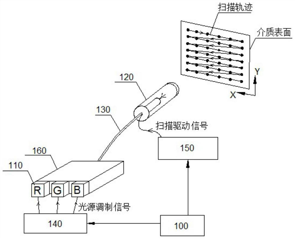
[0047] Such as Figure 2a Shown is an illustrative scanning display module, which mainly includes:

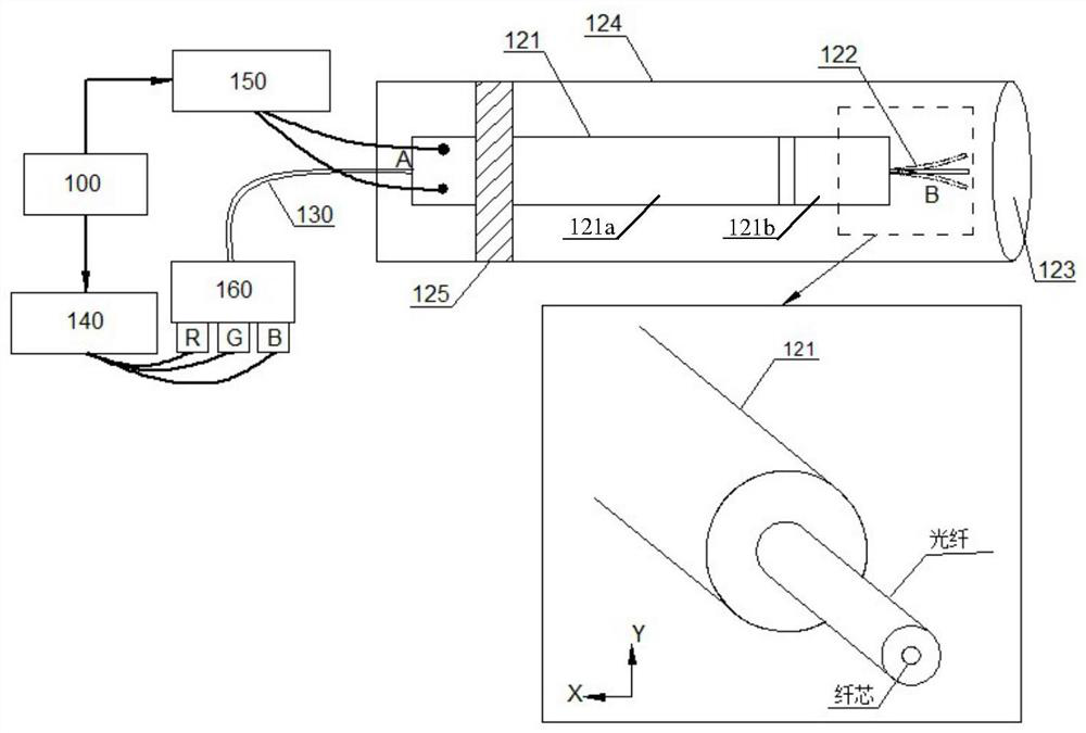
[0048] A processor 100 , a laser group 110 , a fiber scanner 120 , a transmission fiber 130 , a light source modulation circuit 140 , a scanning driving circuit 150 and a beam combining unit 160 . in,

[0049] The processor 100 may be a graphics processing unit (Graphics Processing Unit, GPU), a central processing unit (Central Processing Unit, CPU) or other chips or circuits with control functions and image processin...


PUM


Abstract

The embodiment of the invention discloses a scanning actuator, an optical fiber scanner and a scanning display module, wherein a first actuating part does not perform bending vibration, but is driven by telescopic vibration of an actuating unit or a motor, the whole rotating part periodically swings at a set frequency within a certain angle range by taking a certain specific position as a rotating center, a second actuating part is further driven to swing in the first direction, and the second actuating part can perform bending vibration in the second direction, so that two-dimensional actuating can be realized by scanning the actuator. According to the embodiment of the invention, the scanning actuator can provide larger driving force, can reduce the coupling effect between the two scanning shafts, and has more advantages in a scene needing approximate power and / or large-size scanning display.

Description

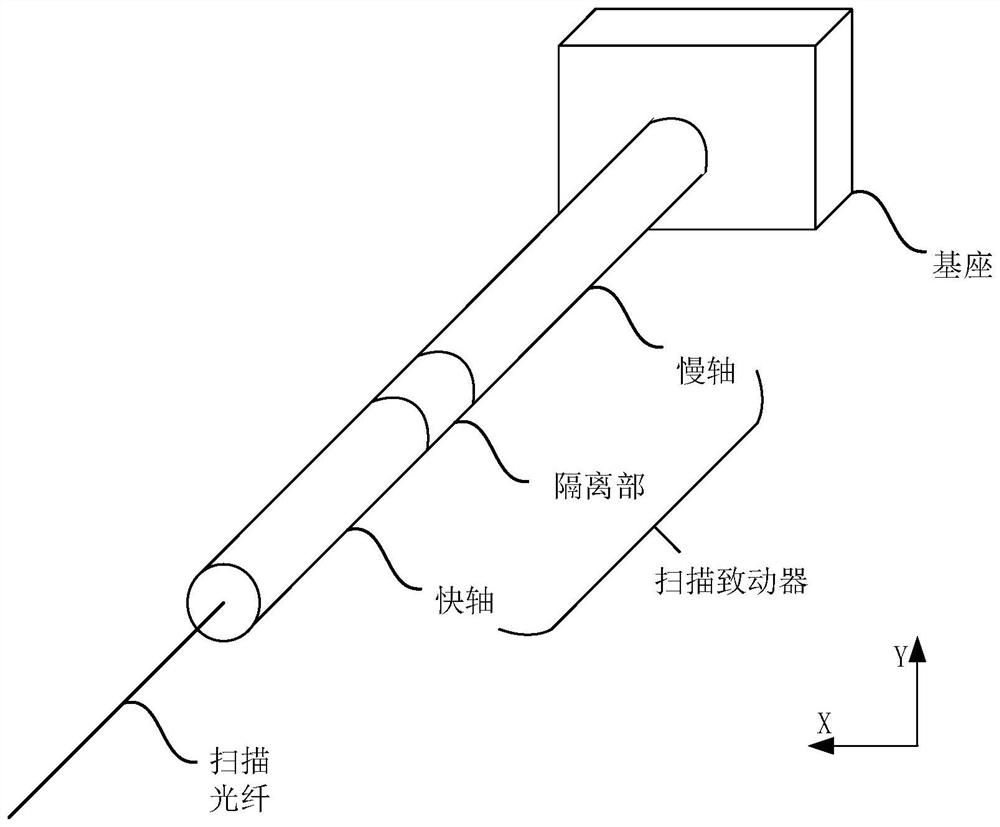
technical field [0001] The present application relates to the technical field of scanning display, in particular to a scanning actuator, an optical fiber scanner and a scanning display module. Background technique [0002] As an emerging display technology, scanning display imaging can be used in various display scenarios such as projection display and near-eye display. [0003] Scanning display imaging can be realized not only by digital micromirror device (Digital Micromirror Device, DMD), which is widely used at present, but also by fiber optic scanner. [0004] A typical fiber optic scanner structure is as follows: figure 1 As shown, the optical fiber scanner mainly includes: a scanning actuator adopting a fast-slow axis structure, and an optical fiber for scanning out light. The scanning actuator fixed on the base includes a slow axis, a partition, and a fast axis in sequence from the back to the front, wherein the slow axis is used in the first direction (vertical di...

Claims


Application Information

Patent Timeline
Patent Type & Authority Applications(China)
IPC IPC(8): G02B26/10
CPCG02B26/103
Inventor 宋海涛其他发明人请求不公开姓名
Owner CHENGDU IDEALSEE TECH
Learn More