Path fusion planning method for passage area, robot and chip

A traffic area and path technology, applied in the direction of instruments, two-dimensional position/channel control, vehicle position/route/altitude control, etc., can solve errors, sensor cumulative error visual map optimization, and obstacle grids that cannot be bypassed, etc. problem, to achieve the effect of increasing the success rate

Pending Publication Date: 2021-07-23
AMICRO SEMICON CORP
View PDF0 Cites 1 Cited by
  • Summary
  • Abstract
  • Description
  • Claims
  • Application Information

AI Technical Summary

Problems solved by technology

When the robot enters these narrow passages, due to the slippage of the robot, the cumulative error of the sensor used for positioning, or the error caused by the optimization of the visual map, the robot is easy to mark these narrow passages as occupied by obstacles on the real-time grid map. area, causing the entrance of the narrow passage mapped to the grid map built by the robot to be blocked, but not actually blocked in the actual motion scene
Therefore, the conventional path search algorithm cannot bypass the grid of obstacles marked by map errors, which is not conducive to robot navigation into and out of such passable areas where marking errors are prone to occur due to narrow passages.

Method used


Image

  • Path fusion planning method for passage area, robot and chip
  • Path fusion planning method for passage area, robot and chip

Examples


Embodiment Construction

[0027] The specific embodiments of the present invention will be further described below in conjunction with the accompanying drawings.

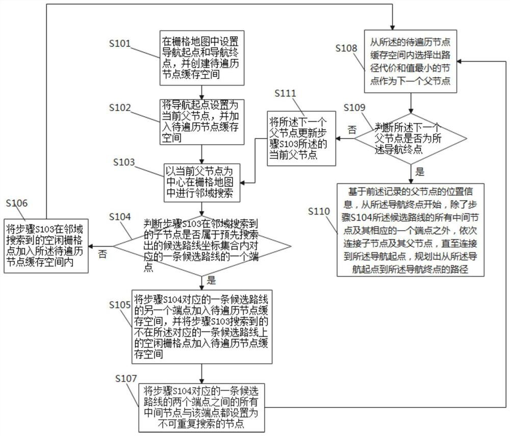
[0028] It should be noted that those skilled in the art can understand that the environment information around the current position of the robot is marked in the grid map, and the grids in the map area constructed by the robot include those marked as free, occupied and Unknown (unknown) three states; These grids are represented by grid points in this embodiment, that is, the center point of the grid; the grid points in the idle state refer to the grids that are not occupied by obstacles, which are accessible to the robot. The grid position points of , are free grid points, which can form an unoccupied area; the occupied grid points refer to the grids occupied by obstacles, which are obstacle grid points, and can form an occupied area; unknown grid points A point refers to a grid area where the specific situation is not clear in the process o...


PUM


Abstract

The invention discloses a path fusion planning method for a passage area, a robot and a chip, and the robot searches candidate paths for fusion in a narrow channel with many obstacles in advance. Then, the path fusion planning method is used for fusing a heuristic search algorithm and the candidate paths meeting the search conditions to plan an overall navigation path, and map grid marking errors are overcome, so that the navigation path planning problem of a robot in a passable area where marking errors are likely to be generated due to the fact that channels in a grid map are narrow is solved.

Description

technical field [0001] The invention relates to the technical field of robot path planning, and relates to a path fusion planning method for a passing area, a robot and a chip. Background technique [0002] Mobile robots in the prior art are a class of robots that use sensors to autonomously detect the surrounding environment, use controllers to determine the movement of the machine body, and use actuators (such as wheels) to realize the movement. The cleaning robot of the prior art often moves to the narrow passage formed by the restriction between various furniture components such as the four feet of the stool in the home environment, the entrance of the tea table, and the narrow passage formed by the opening of the door of the room. When the robot enters these narrow passages, due to the slippage of the robot, the cumulative error of the sensor used for positioning, or the error caused by the optimization of the visual map, the robot is easy to mark these narrow passages ...

Claims


Application Information

Patent Timeline
IPC IPC(8): G05D1/02
CPCG05D1/0223G05D1/0221G05D1/0289G05D1/0295G05D1/0276
Inventor 孙永强李永勇杨武
Owner AMICRO SEMICON CORP
Why Eureka
Try Eureka