
Energy reduction device, energy reduction method, electronic equipment and computer readable storage medium

A technology of energy reduction and energy reduction sheet, which is applied in radiation/particle processing, nuclear engineering, etc., and can solve problems such as the inability to meet the continuous change of energy requirements

Pending Publication Date: 2021-07-23
CHINA ELECTRONICS PROD RELIABILITY & ENVIRONMENTAL TESTING RES INST
View PDF5 Cites 0 Cited by
  • Summary
  • Abstract
  • Description
  • Claims
  • Application Information

AI Technical Summary

Problems solved by technology

[0004] Based on this, it is necessary to provide an energy reduction device, an energy reduction method, an electronic device, and a computer-readable storage medium for the problem that the energy reduction device can only achieve one energy reduction effect, but cannot meet the demand for continuous energy changes.

Method used


Image

  • Energy reduction device, energy reduction method, electronic equipment and computer readable storage medium
  • Energy reduction device, energy reduction method, electronic equipment and computer readable storage medium
  • Energy reduction device, energy reduction method, electronic equipment and computer readable storage medium

Examples


Embodiment 1

[0044] This embodiment provides an energy reducing device for reducing the energy of charged particles.

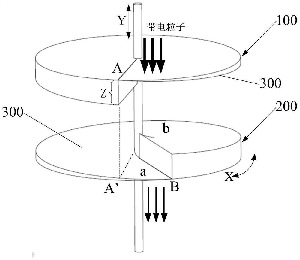
[0045] refer to figure 1 , the energy-reducing device provided in this embodiment includes a first energy-reducing sheet 100 and a second energy-reducing sheet 200 arranged coaxially, and the thickness of the first energy-reducing sheet 100 is along the circumferential direction of the first energy-reducing sheet 100 X shows a spiral changing trend, and the thickness of the second energy-reducing sheet 200 shows a spiral-shaped changing trend along the circumferential direction X of the second energy-reducing sheet 200;

[0046] When at least one of the first energy-reducing sheet 100 and the second energy-reducing sheet 200 rotates along the axis, the first energy-reducing sheet 100 and the second energy-reducing sheet 200 in the axial direction Y The stacking thickness showed a monotonous trend.

[0047] Since the first energy-reducing sheet 100 and the second energy-r...

Embodiment 2

[0072] This embodiment provides an energy reduction method, which is applied to the energy reduction device described in Embodiment 1 to reduce the energy of charged particles.

[0073] refer to figure 2 , the energy reduction method provided in this embodiment includes the following steps:

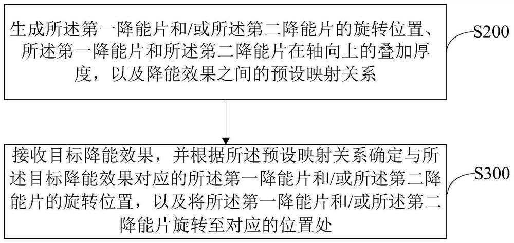
[0074] Step S200, generating the rotational position of the first energy-reducing sheet 100 and / or the second energy-reducing sheet 200, the position of the first energy-reducing sheet 100 and the second energy-reducing sheet 200 in the axial direction Y Overlay thickness, and the preset mapping relationship between energy-reducing effects;

[0075] Step S300, receiving a target energy-reducing effect, and determining the rotational position of the first energy-reducing sheet 100 and / or the second energy-reducing sheet 200 corresponding to the target energy-reducing effect according to the preset mapping relationship, And rotate the first energy-reducing sheet 100 and / or the second ene...

Embodiment 3

[0087] The embodiment of the present application provides an electronic device, such as Figure 4 As shown, it includes a memory 600 and a processor 700, and the memory 600 and the processor 700 are connected to each other by communication, and may be connected through a bus or other methods. Figure 4 Take connection via bus as an example.

[0088] The processor 700 may be a central processing unit (Central Processing Unit, CPU). The processor 600 may also be other general-purpose processors, digital signal processors (Digital Signal Processor, DSP), application-specific integrated circuits (Application Specific Integrated Circuit, ASIC), field-programmable gate array (Field-Programmable Gate Array, FPGA) or Other chips such as programmable logic devices, discrete gate or transistor logic devices, discrete hardware components, or combinations of the above-mentioned types of chips.

[0089] The memory 600, as a non-transitory computer-readable storage medium, can be used to ...


PUM


Abstract

The invention relates to the technical field of energy reduction, and particularly discloses an energy reduction device, an energy reduction method, electronic equipment and a computer readable storage medium. The energy reduction device comprises a first energy reduction piece and a second energy reduction piece which are coaxially arranged, the thickness of the first energy reduction piece is in a spiral change trend in the circumferential direction of the first energy reduction piece, and the thickness of the second energy reduction piece is in a spiral change trend in the circumferential direction of the second energy reduction piece. When at least one of the first energy reduction piece and the second energy reduction piece rotates along the shaft, the superposition thickness of the first energy reduction piece and the second energy reduction piece in the axial direction is in a monotonous change trend. When the first energy reduction sheet and / or the second energy reduction sheet rotate along the shaft, the combined and superposed thickness of the first energy reduction piece and the second energy reduction piece in the axial direction is continuously changed and is in a monotonous change trend, so that when the energy reduction device is arranged on an incident path of charged particles, the energy of the charged particles can be continuously reduced through the energy reduction device, and the continuous adjustment effect of charged particle energy is realized.

Description

technical field [0001] The present invention relates to the field of energy reduction technology, in particular to an energy reduction device, an energy reduction method, electronic equipment and a computer-readable storage medium. Background technique [0002] In general, high LET (Linear Energy Transfer, linear energy transfer) ion irradiation experiments need to be carried out on a heavy ion cyclotron, the type and initial energy of the heavy ions obtained are fixed, and the initial LET value of heavy ions during the test is It is also a definite value. When the LET value of the ion needs to be changed, it is usually necessary to reduce the energy of the heavy ion. At present, the commonly used method is to use energy-degrading sheets of different materials and thicknesses to reduce the energy of heavy ions, thereby changing the LET value of heavy ions after passing through the energy-degrading sheets. Generally, the higher the atomic number, the better the energy reduct...

Claims


Application Information

Patent Timeline
IPC IPC(8): G21K1/00
CPCG21K1/00
Inventor 雷志锋张战刚黄云李键坷彭超何玉娟
Owner CHINA ELECTRONICS PROD RELIABILITY & ENVIRONMENTAL TESTING RES INST
Learn More