Isolation grounding switch and operating mechanism thereof

A technology for isolating grounding switches and operating mechanisms, applied in grounding switches, contact operating mechanisms, electrical switches, etc., to achieve the effects of convenient operation, improved user experience, and reduced economic losses

Active Publication Date: 2021-07-23
平高集团威海高压电器有限公司 +2
View PDF12 Cites 0 Cited by
  • Summary
  • Abstract
  • Description
  • Claims
  • Application Information

AI Technical Summary

Problems solved by technology

[0005] The purpose of the present invention is to provide an operating mechanism for an isolating grounding switch to solve the technical problem in the prior art that when a single-phase transformer fails, it is necessary to open the three-phase switch to perform maintenance; the purpose of the present invention is to provide a An isolating grounding switch to solve the technical problem in the prior art that when a single-phase transformer fails, it is necessary to open the three-phase equally for maintenance

Method used


Image

  • Isolation grounding switch and operating mechanism thereof
  • Isolation grounding switch and operating mechanism thereof

Examples


Embodiment 1

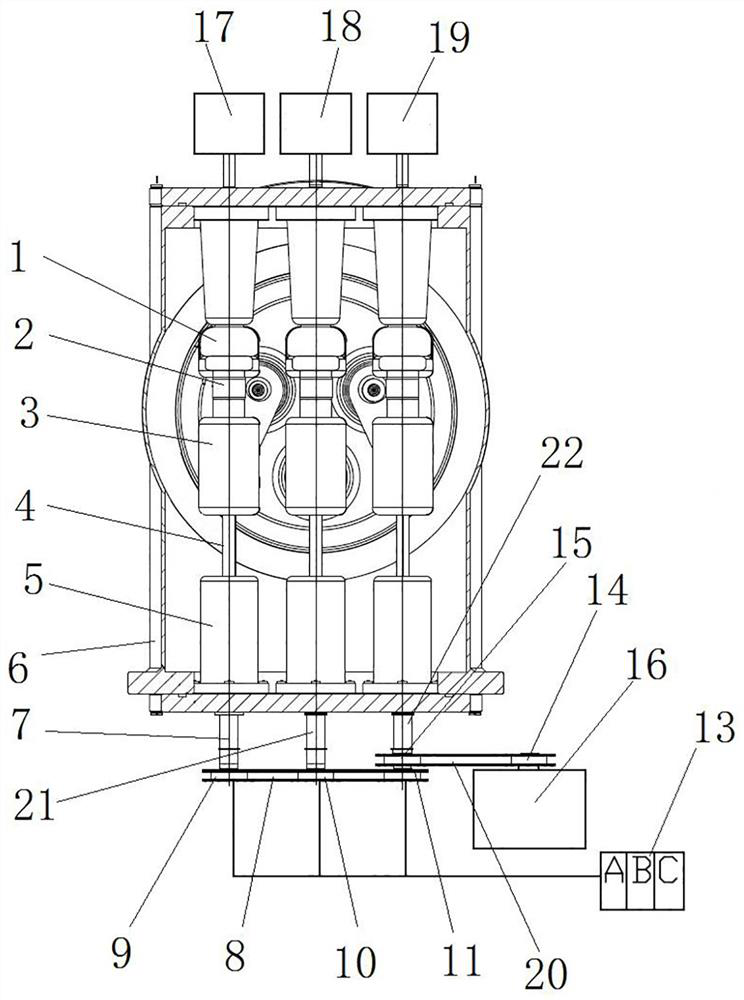
[0049] Such as figure 1 As shown, the isolation grounding switch includes a cylinder body 6, and the cylinder body 6 is provided with three sets of gate contact seats 1, three sets of moving contacts 2, three sets of intermediate contact seats 3, three sets of screw rods 4 and three sets of ground contact seats 5; The closing contact seat 1, the intermediate contact seat 3 and the grounding contact seat 5 are arranged at intervals in the axial direction of the cylinder body 6, and the movable contact 2 is electrically conductive and slidably assembled in the intermediate contact seat 3 along the axial direction of the cylinder body 6. The corresponding screw rod 4 is threaded, and the moving contact 2 is driven to slide through the rotation of the screw rod 4, so that the moving contact 2 is in contact with the closing contact seat 1, the moving contact 2 is separated from the closing contact seat 1, and the moving contact 2 is in contact with the closing contact seat 1. The g...

Embodiment 2

[0061] The difference between this embodiment and Embodiment 1 is that in Embodiment 1, the three clutches 12 are all electromagnetic clutches, and the controller 13 remotely controls the clutch 12 to work; while in this embodiment, the three clutches are all mechanical clutches , the mechanical clutch works through manual control.

Embodiment 3

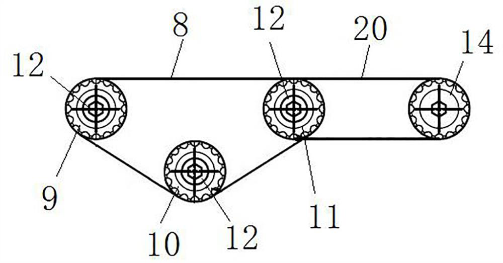
[0063] The difference between this embodiment and Embodiment 1 is that in Embodiment 1, the A-phase driving wheel is the A-phase sprocket 9, the B-phase driving wheel is the B-phase sprocket 10, and the C-phase driving wheel is the C-phase sprocket 11. , A-phase sprocket 9, B-phase sprocket 10 and C-phase sprocket 11 are connected through the interphase chain 8 to realize synchronous rotation; and in this embodiment, the A-phase drive wheel is an A-phase gear, and the B-phase drive The wheel is a B-phase gear, the C-phase driving wheel is a C-phase gear, and the A-phase gear, B-phase gear, and C-phase gear are connected through an intermediate gear to realize synchronous rotation.


PUM


Abstract

The invention relates to an isolation grounding switch and an operating mechanism thereof. The operating mechanism of the isolation grounding switch comprises an A-phase driving shaft, a B-phase driving shaft and a C-phase driving shaft which are arranged side by side; an A-phase driving wheel is mounted on the A-phase driving shaft, a B-phase driving wheel is mounted on the B-phase driving shaft, and a C-phase driving wheel is mounted on the C-phase driving shaft; the A-phase driving wheel, the B-phase driving wheel and the C-phase driving wheel are in transmission connection to realize synchronous rotation; a driving device is in transmission connection with one of the A-phase driving shaft, the B-phase driving shaft and the C-phase driving shaft; three clutches are also arranged between the A-phase driving wheel and the A-phase driving shaft, between the B-phase driving wheel and the B-phase driving shaft and between the C-phase driving wheel and the C-phase driving shaft respectively. The maintenance of the transformer or other equipment of the fault phase is realized under the condition of uninterruptible power supply, the user experience is improved, and meanwhile, the economic loss is also reduced.

Description

technical field [0001] The invention relates to an isolating grounding switch and its operating mechanism. Background technique [0002] The gas-insulated metal-enclosed switch has the characteristics of high reliability, maintenance-free, miniaturization and no influence from the environment. Among them, the isolation grounding switch is an important component of the gas-insulated metal-enclosed switch. The isolating and grounding switch is driven by the operating mechanism through the transmission parts to realize the closing, opening and grounding functions of the isolating and grounding switch. [0003] The Chinese invention patent application with the application publication number CN102254714A discloses an operating mechanism of a direct-acting three-position isolating switch, including drive shaft A, drive shaft B, and drive shaft C installed side by side, drive shaft A, drive shaft B , and the drive shaft C are respectively equipped with sprocket A, sprocket B and s...

Claims


Application Information

Patent Timeline
Patent Type & Authority Applications(China)
IPC IPC(8): H01H31/02H01H31/04H01H31/00H01H3/54
CPCH01H31/02H01H31/04H01H31/003H01H3/54
Inventor 刘振峰王宁邹雪平于慧波谭传亮黄腾刘胜杰周茂欣卢素梅孙建峰孙智慧毕颖林王飞刘莉刘辉赵晓迪韩羽张帅谭金洪王猛周雪松徐真真张晓辉刘子宁史翠斐李俊峰魏明艳
Owner 平高集团威海高压电器有限公司
Why Eureka
Try Eureka