High-performance full-duplex communication circuit

A communication circuit and full-duplex technology, applied in the field of communication, can solve problems such as unfavorable signal reception and decoding, and unsatisfactory transmission performance, so as to achieve maximum reception gain, stable reception and transmission signal performance, and improved reception performance.

Pending Publication Date: 2021-07-23
GUANGDONG KUANPU TECH CO LTD
View PDF0 Cites 9 Cited by
  • Summary
  • Abstract
  • Description
  • Claims
  • Application Information

AI Technical Summary

Problems solved by technology

At present, the transmission performance of high-performance full-duplex communication circuits is not very ideal. During the processing of transmission signals, clutter radiation s

Method used


Image

  • High-performance full-duplex communication circuit
  • High-performance full-duplex communication circuit
  • High-performance full-duplex communication circuit

Examples


Embodiment 1

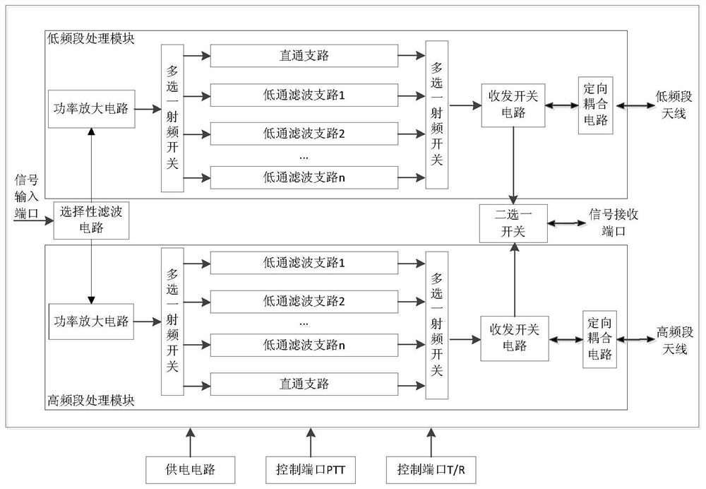
[0039] Such as Figure 1 to Figure 7 As shown, a high-performance full-duplex communication circuit in this embodiment includes a low-frequency processing module, a high-frequency processing module, a signal input port, a signal receiving port, a low-frequency antenna, and a high-frequency antenna; the low-frequency processing module and the high-frequency The processing modules all include a power amplifier circuit, a straight-through filter circuit and a transceiver switch circuit connected in sequence;

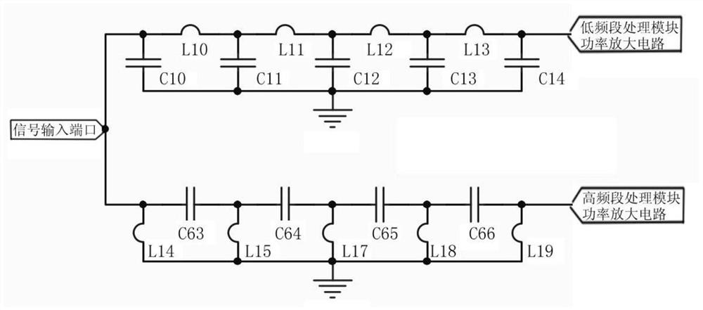
[0040] The power amplifying circuit of the low frequency processing module and the power amplifying circuit of the high frequency processing module are respectively connected to the signal input port through a selective filter circuit; The transceiver switch circuit of the frequency band processing module is connected to the high frequency antenna bidirectional signal through a directional coupling circuit; the transceiver switch circuit of the low frequency band processing...

Embodiment 2

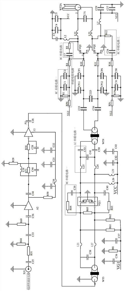
[0063] In this embodiment, a high-performance full-duplex communication circuit is illustrated by taking the 30-500M band signal as an example, as Figure 8shown. The low-frequency band processing module processes 30-100M band signals, and the low-frequency band processing module processes 110-500M band signals. In the low-frequency band processing module, the power amplifier circuit is a 30-100M power amplifier circuit, and the straight-through filter circuit includes a straight-through branch and three low-pass filter branches; the three low-pass filter branches are respectively 30-45MHz low-pass filter branches , 45-70MHz low-pass filter branch and 70-100MHz low-pass filter branch. In the high-frequency band processing module, the power amplifier circuit is a 110-500M power amplifier circuit, and the straight-through filter circuit includes a straight-through branch and three low-pass filter branches; the three low-pass filter branches are respectively 110-180MHz low-pass ...


PUM


Abstract

The invention provides a high-performance full-duplex communication circuit. The high-performance full-duplex communication circuit is characterized by comprising a low-band processing module and a high-band processing module; each of the low-band processing module and the high-band processing module comprises a power amplification circuit, a straight-through filter circuit and a transmit-receive switch circuit which are connected in sequence; the power amplification circuit of the low-band processing module and the power amplification circuit of the high-band processing module are connected with a signal input port through a selective filter circuit; the transmit-receive switch circuit of the low-band processing module is in bidirectional signal connection with a low-band antenna through a directional coupling circuit; the transmit-receive switch circuit of the high-band processing module is in bidirectional signal connection with a high-band antenna through a directional coupling circuit; the transmit-receive switch circuit of the low-band processing module and the transmit-receive switch circuit of the high-band processing module are also connected with a signal receiving port through an alternative switch circuit. The communication circuit can work in a full-duplex state, and the signal transmitting and receiving performance can be improved.

Description

technical field [0001] The invention relates to the technical field of communication, more specifically, to a high-performance full-duplex communication circuit. Background technique [0002] Full duplex (Full Duplex) is a term for communication transmission. Communication allows data to be transmitted simultaneously in two directions, which is equivalent to the combination of two simplex communication methods in capability. At present, the transmission performance of high-performance full-duplex communication circuits is not very ideal. The clutter radiation signal is generated during the processing of the transmission signal, which leads to the presence of interference signals before the signal is transmitted by the antenna, which is not conducive to the subsequent reception and decoding of the signal. Therefore, a full-duplex communication circuit with good emission performance should be designed. Contents of the invention [0003] In order to overcome the disadvantag...

Claims


Application Information

Patent Timeline
IPC IPC(8): H04B1/40H04L5/14
CPCH04B1/40H04L5/14
Inventor 谭灵杰户大伟陈振权
Owner GUANGDONG KUANPU TECH CO LTD
Why Eureka
Try Eureka