Separating device and use of a separating device

A separation device, annular disk technology, applied in separation methods, filtration separation, chemical instruments and methods, etc., can solve problems such as fracture and annular disk damage, and achieve the effects of avoiding rupture, improving robustness, and improving mechanical vibration resistance.

Inactive Publication Date: 2021-07-23
3M INNOVATIVE PROPERTIES CO
View PDF4 Cites 0 Cited by
  • Summary
  • Abstract
  • Description
  • Claims
  • Application Information

AI Technical Summary

Problems solved by technology

[0007] During the process of installing the screen into the wellbore, i.e. inserting the screen, passing it downhole through the narrow passage and setting it into its final position, there is a risk of subjecting the screen to mechanical shocks which can cause Damage to annular discs made of brittle hard material
It has been observed that screens according to US 8,662,167 B2 and WO 2016 / 018821 A1 may show failures during installation due to ceramic rings breaking after being dropped from a height of eg 30 cm or by a shocking process

Method used


Image

  • Separating device and use of a separating device
  • Separating device and use of a separating device
  • Separating device and use of a separating device

Examples


Embodiment Construction

[0033] A preferred embodiment and details of the separation device of the present disclosure will be explained in more detail below with reference to the accompanying drawings.

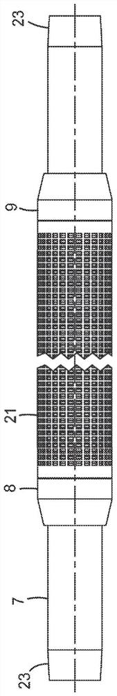
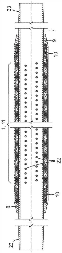
[0034] figure 1 An overall view of the separation device according to the present disclosure is shown. figure 2 A cross-sectional view of the separation device according to the present disclosure is shown. The separation device according to the present disclosure includes a stack of at least three annular discs, which defines a central annular region 1, 11 along the central axis. Preferably, the stack of at least three annular discs is a concentric stack. The separation device includes a perforation tube 7, an annular disk stacked on the perforation tube. The perforation tube 7 having perforations 22 is located within the stacks 1, 11 of the annular disc, and is also referred to below as a base tube. A thread 23 is typically provided at both ends of the perforation tube 7, by which the separation device ...


PUM

PropertyMeasurementUnit
yield strengthaaaaaaaaaa
thicknessaaaaaaaaaa
sizeaaaaaaaaaa

Abstract

The present disclosure relates to a separating device for removing solid particles from fluids having an improved resistance to mechanical shocks, and to the use of said separating device for removing solid particles from fluids.

Description

Technical field [0001] The present disclosure relates to a separation device for removing solid particles from fluid. Background technique [0002] Such separation devices are required in many oil and natural gas mining wells. Mineral oils and natural gas stores in naturally occurring underground reservoirs, oil or natural gas is distributed in more or less porous and permeable mineral layers. The purpose of each oil or natural gas drilling is to reach the reservoir and take advantage of it in a manner, ie, as much as possible, can only take advantage of oil and natural gas, and minimize or even completely avoid undesirable by-products. An undesirable by-product in oil and gas extraction includes solid particles, such as sand, and other mineral particles, by liquid flow or gas stream from the reservoir, such as sand and other mineral particles. [0003] Since the ore sand is usually abrasive, this solid flow into the production line and the pump will cause a considerable undesira...

Claims


Application Information

Patent Timeline
Patent Type & Authority Applications(China)
IPC IPC(8): E21B43/08B01D29/46
CPCE21B43/08E21B43/086B01D29/46
Inventor 弗兰克·梅施克彼得·巴尔特
Owner 3M INNOVATIVE PROPERTIES CO
Why Eureka
Try Eureka