Plastic bag cut-off device

A technology for cutting devices and plastic bags, applied in packaging, bag-making operations, transportation and packaging, etc., can solve the problem of large device footprint, avoid manual labor, reduce operating steps, and ensure production efficiency and service life. Effect

Inactive Publication Date: 2021-07-27
怀宁县日升塑业有限公司
View PDF0 Cites 0 Cited by
  • Summary
  • Abstract
  • Description
  • Claims
  • Application Information

AI Technical Summary

Problems solved by technology

[0007] The object of the present invention is to provide a plastic bag cutting device to solve the problem that the existing cutting device is usually equipped with a corresponding winding mechanism, but because the winding mechanism is often only provided with a single set of winding rollers, resulting in During the process of rewinding the fresh-keeping bag, the device needs to suspend the operation of the machine several times to complete the rewinding operation. Since the traditional cutting device does not have the function of adjusting its working position, it usually requires the staff to adjust the operation of the device. The working position can be effectively adjusted only after the cutting components are disassembled and reinstalled. Traditional cutting devices usually divide the power-off cutting machine and sealing machine into two independent components, resulting in the problem that the device itself occupies a large area.

Method used


Image

  • Plastic bag cut-off device
  • Plastic bag cut-off device
  • Plastic bag cut-off device

Examples


Embodiment 1

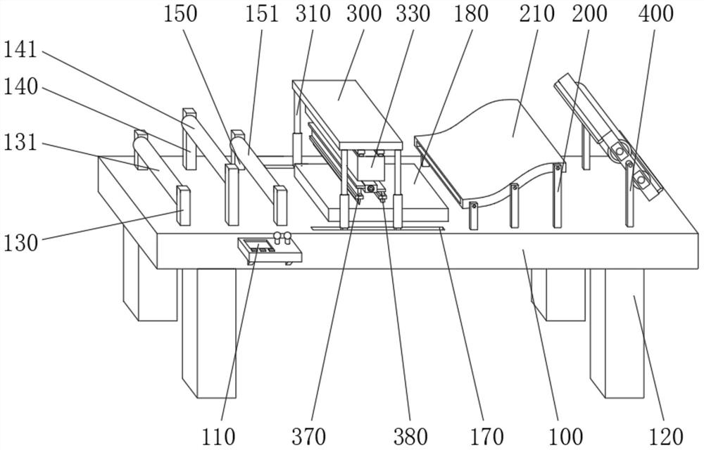
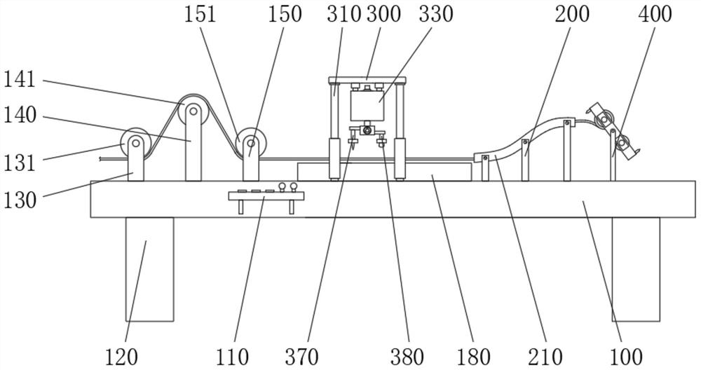
[0030] see Figure 1-2 and Figure 6-7, the present invention provides a technical solution: a plastic bag cutting device, including a base 100, two sets of fixing frames 200, a top plate 300 and two side plates 400, and the two sets of fixing frames 200 are respectively fixedly connected to the top of the base 100 On the front and rear sides, the top plate 300 is located on the left side of the two sets of fixing frames 200, and the two side plates 400 are respectively fixedly connected to the front and rear sides of the top of the base 100, and are located on the right side of the two sets of fixing frames 200, and the front of the base 100. The left side of the side wall is fixedly connected with the console 110 by bolts, the four corners of the bottom of the base 100 are welded with pillars 120, the top left side of the base 100 is fixedly connected with the first bracket 130, and the internal rotation of the first bracket 130 is connected There is a conveying roller 131,...

Embodiment 2

[0033] see Figure 1-3 and Figure 5 , the present invention provides a technical solution: a plastic bag cutting device, including a base 100, two sets of fixing frames 200, a top plate 300 and two side plates 400, and the two sets of fixing frames 200 are respectively fixedly connected to the top of the base 100 On the front and rear sides, the top plate 300 is located on the left side of the two sets of fixing frames 200, and the two side plates 400 are respectively fixedly connected to the front and rear sides of the top of the base 100, and are located on the right side of the two sets of fixing frames 200, and the front of the base 100. The left side of the side wall is fixedly connected with the console 110 by bolts, the four corners of the bottom of the base 100 are welded with pillars 120, the top left side of the base 100 is fixedly connected with the first bracket 130, and the internal rotation of the first bracket 130 is connected There is a conveying roller 131, ...

Embodiment 3

[0036] see Figure 1-4 , the present invention provides a technical solution: a plastic bag cutting device, including a base 100, two sets of fixing frames 200, a top plate 300 and two side plates 400, and the two sets of fixing frames 200 are respectively fixedly connected to the top of the base 100 On the front and rear sides, the top plate 300 is located on the left side of the two sets of fixing frames 200, and the two side plates 400 are respectively fixedly connected to the front and rear sides of the top of the base 100, and are located on the right side of the two sets of fixing frames 200, and the front of the base 100. The left side of the side wall is fixedly connected with the console 110 by bolts, the four corners of the bottom of the base 100 are welded with pillars 120, the top left side of the base 100 is fixedly connected with the first bracket 130, and the internal rotation of the first bracket 130 is connected There is a conveying roller 131, the top of the ...


PUM


Abstract

The invention discloses a plastic bag cut-off device, and belongs to the technical field of plastic bag processing and production equipment. The plastic bag cut-off device comprises a base, two sets of fixing frames, a top plate and two side plates, wherein the two sets of fixing frames are fixedly connected with the front side and the rear side of the top of the base respectively, the top plate is located at the left sides of the two sets of fixing frames, and the two side plates are fixedly connected with the front side and the rear side of the top of the base respectively. The plastic bag cut-off device is reasonable in structural design, compared with a traditional device, the plastic bag cut-off device is provided with two sets of winding mechanisms, the purpose of collecting freshness protection bags can be achieved without closing a working process of the plastic bag cut-off device, moreover, the working position of the device can be rapidly adjusted according to the actual requirements of sites, the operation content of actual use of the device is simplified, extra labor cost is avoided, and meanwhile, according to the device, a cut-off tool and a heating sealing strip can be synchronously installed so that the device can have the effect of one machine with two purposes, the actual occupied area of the device is reduced, and the application range of actual use of the device is expanded.

Description

technical field [0001] The invention relates to the technical field of plastic bag processing and production equipment, in particular to a plastic bag cutting device. Background technique [0002] Plastic bags usually refer to bags made of plastic as the main raw material. They are indispensable items in people's daily life and are often used to hold other items. Among them, fresh-keeping bags are one of the most commonly used items in plastic bag products. In the production process, breakpoint cutting machines and sealing machines are usually used to process fresh-keeping bag rolls. [0003] However, there are certain deficiencies in the actual use of the cutting device in the existing market: [0004] 1. The existing cutting device is usually equipped with a corresponding winding mechanism, but because the winding mechanism is often only equipped with a single set of winding rollers, the device needs to suspend the operation of the machine many times during the winding pr...

Claims


Application Information

Patent Timeline
Patent Type & Authority Applications(China)
IPC IPC(8): B31B70/16B31B70/64B31B70/74
CPCB31B70/16B31B70/64B31B70/74
Inventor 汪传红
Owner 怀宁县日升塑业有限公司
Why Eureka
Try Eureka