Screen printing plate adjusting mechanism and printing machine

A technology of adjusting mechanism and screen, applied in screen printing machine, printing machine, screen printing and other directions, can solve the problems of increasing the adjustment angle error, increasing the size of the mounting plate, affecting the stability of the rotating adjustment mechanism, etc.

Pending Publication Date: 2021-07-27
常州捷佳创智能装备有限公司
View PDF0 Cites 1 Cited by
  • Summary
  • Abstract
  • Description
  • Claims
  • Application Information

AI Technical Summary

Problems solved by technology

[0002] At present, most photovoltaic manufacturers use the screen printing method to prepare the electrodes and electric fields of the cells, which requires the alignment of the cells and the screen printing screen. This type of alignment has a high precision and cannot be done by manpower.
[0003] In the related art, the angle adjustment is realized by converting the motion of the linear motor into the motion of the arc-shaped guide rail, which requires the cooperation of multiple parts, which is easy to increase the error of the adjustment angle. position, which in turn increases the size of the mounting plate on the rotation adjustment mechanism and increases the gravity of the head, which may easily cause the center of gravity of the rotation adjustment mechanism to deviate, affect the stability of the rotation adjustment mechanism in the horizontal direction, and further affect the printing effect of the battery sheet

Method used


Image

  • Screen printing plate adjusting mechanism and printing machine
  • Screen printing plate adjusting mechanism and printing machine
  • Screen printing plate adjusting mechanism and printing machine

Examples


Embodiment Construction

[0049] In order to understand the above-mentioned purpose, features and advantages of the present invention more clearly, the present invention will be further described in detail below in conjunction with the accompanying drawings and specific embodiments. It should be noted that, in the case of no conflict, the embodiments of the present application and the features in the embodiments can be combined with each other.

[0050] In the following description, many specific details are set forth in order to fully understand the present invention. However, the present invention can also be implemented in other ways than described here. Therefore, the protection scope of the present invention is not limited by the specific implementation disclosed below. Example limitations.

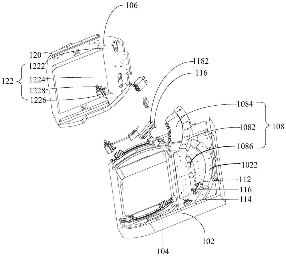
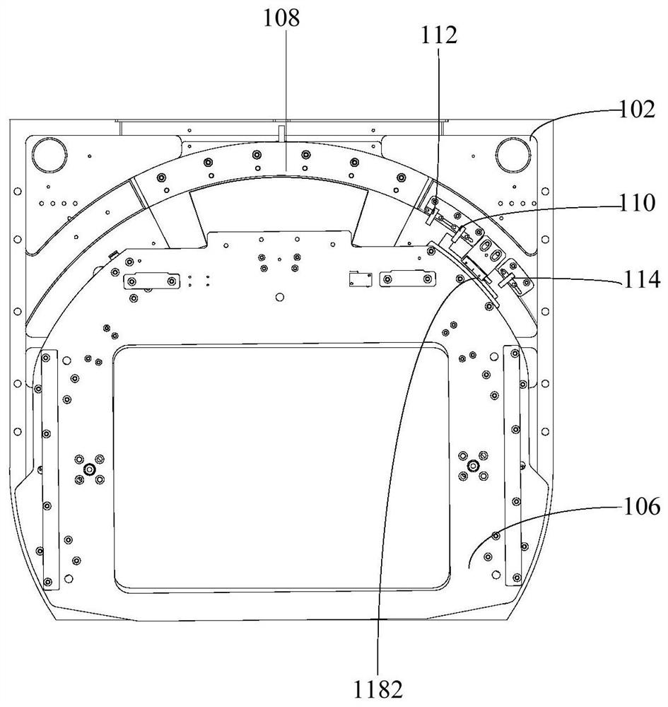
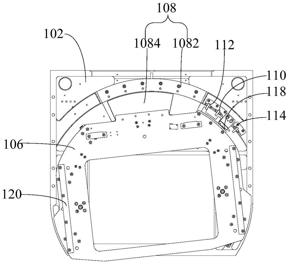
[0051] Refer below Figure 1 to Figure 9 A screen adjustment mechanism and a printing machine provided according to some embodiments of the present invention will be described.

[0052] Such as figure 1 As...


PUM


Abstract

The invention provides a screen printing plate adjusting mechanism and a printing machine. The screen printing plate adjusting mechanism comprises a base, a guide structure, a mounting plate and a driving device. The guide structure is arranged on the base. The mounting plate is movably connected with the base through the guide structure. The driving device at least comprises a stator end and a rotor end, the stator end is connected with the base, the rotor end is connected with the mounting plate, and the driving device drives the mounting plate to do arc-shaped motion along the guide structure. The driving device directly drives the mounting plate to perform angle adjustment, so that the transmission stage number is reduced, the angle adjustment error of the mounting plate is reduced, mounting stations for mounting other structures are omitted, the overall weight of the screen printing plate adjusting mechanism is further reduced, the gravity center of the screen printing plate adjusting mechanism can be effectively prevented from deviating, and therefore, the stability of angle adjustment is improved.

Description

technical field [0001] The invention relates to the technical field of printing machines, in particular to a screen adjustment mechanism and a printing machine. Background technique [0002] At present, most photovoltaic manufacturers use the screen printing method to prepare the electrodes and electric fields of the cells, which requires the alignment of the cells and the screen printing screen. This type of alignment has a high precision and cannot be done by manpower. . [0003] In the related art, the angle adjustment is realized by converting the motion of the linear motor into the motion of the arc-shaped guide rail, which requires the cooperation of multiple parts, which is easy to increase the error of the adjustment angle. position, which in turn leads to an increase in the size of the mounting plate on the rotation adjustment mechanism and an increase in the gravity of the head, which may easily cause the center of gravity of the rotation adjustment mechanism to d...

Claims


Application Information

Patent Timeline
Patent Type & Authority Applications(China)
IPC IPC(8): B41F15/36B41F15/08
CPCB41F15/08B41F15/36B41P2215/10B41P2215/50
Inventor 左国军胡永涛王明飞王刘佳
Owner 常州捷佳创智能装备有限公司
Why Eureka
Try Eureka