Direct-acting type direct-current relay with movable contact spring

A technology of DC relays and moving reeds, applied in relays, electromagnetic relays, detailed information of electromagnetic relays, etc., can solve problems such as upper circlip breakage, product failure, and lower circlip breakage, etc., to avoid impact and eliminate products. Ineffective effect

Pending Publication Date: 2021-07-27
ZHEJIANG HONGZHOU NEW ENERGY TECH
View PDF0 Cites 0 Cited by
  • Summary
  • Abstract
  • Description
  • Claims
  • Application Information

AI Technical Summary

Problems solved by technology

For DC relays with this structure, on the one hand, the moving iron core and the push rod are fixed by the lower clip spring. During the release process of the relay, due to the spring reaction force and the gravity of the push rod assembly itself, the lower clip spring is prone to breakage. , resulting in failure of the product; on the other hand, the upper circlip is limited by the upper circlip between the moving reed and the push rod. When it is released, the upper circlip will be impacted, and the upper circlip will also break, resulting in product failure; the specific phenomenon is : After the relay is fully engaged, the distance from the lower surface of the upper circlip to the upper surface of the moving reed is the distance of the overtravel, that is, the gap in the moving assembly that is the same as the distance of the overtravel appears on the lower surface of the upper circlip and the moving reed between the surfaces, wherein the moving assembly includes a push rod 101 assembled together, an upper circlip 102, a lower circlip 103, a moving reed 104 and a moving iron core 105. When the coil is powered off, the two springs (contact pressure spring and reaction force spring) the sum of the work done by the reaction force at the overtravel distance and the work done by the gravitational force of the circlip, push rod and moving iron core under the overtravel distance is converted into the kinetic energy of the push rod and upper circlip , when the lower surface of the upper circlip is in contact with the upper surface of the movable reed, the energy impacts on the upper circlip, and the upper circlip may break

Method used


Image

  • Direct-acting type direct-current relay with movable contact spring
  • Direct-acting type direct-current relay with movable contact spring
  • Direct-acting type direct-current relay with movable contact spring

Examples


Embodiment

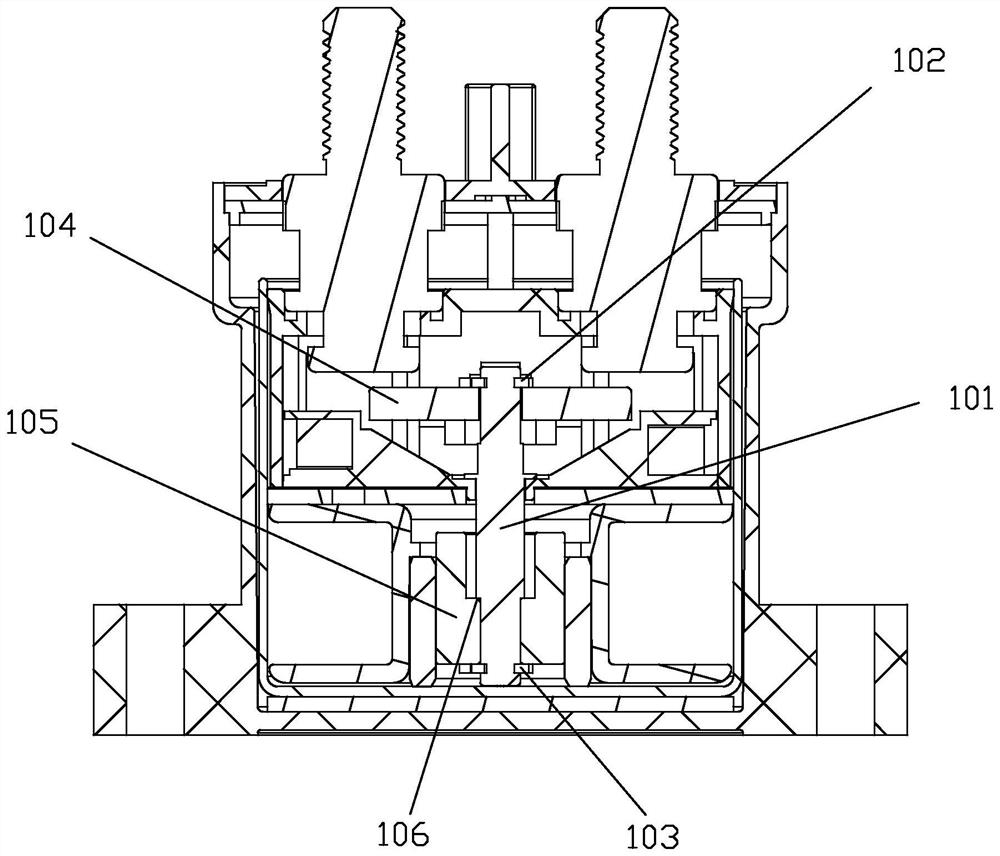
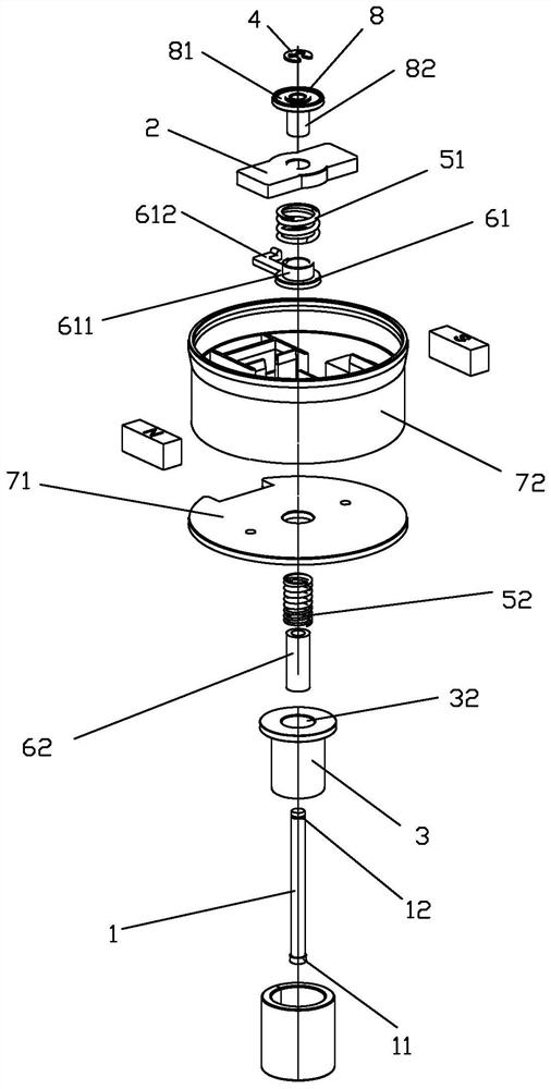
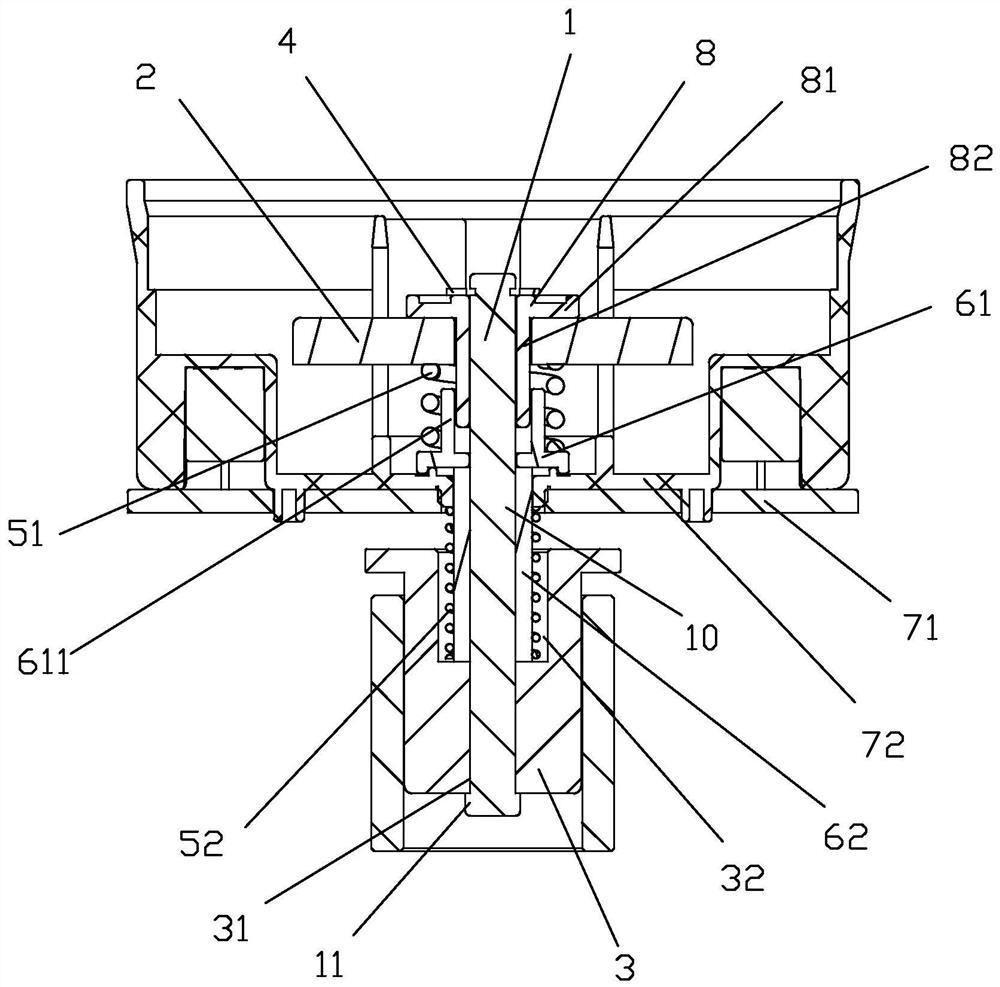
[0030] see Figure 2 to Figure 7As shown, a moving reed direct-acting DC relay of the present invention includes a moving assembly 10 assembled by a push rod 1, a moving reed 2 and a moving iron core 3; the moving assembly 10 also includes an upper Circlip 4 and contact pressure spring 51, the moving reed 2 is movably socketed on the top of the push rod 1 through the upper circlip 4 and contact pressure spring 51, so as to realize overtravel by using the contact pressure spring; Circlip 4 is clamped and fixed on the top of push rod 1 through the card slot 12 at the top of push rod 1 and is limited on the top of the moving reed 2, and the contact pressure spring 51 is fitted on the moving reed 2 The bottom surface of the moving iron core 3 is provided with an iron core hole 31 that can be inserted into the push rod; The convex edge 11 of the core hole 31, the push rod 1 is inserted into the iron core hole 31 of the moving iron core 3 from bottom to top, the convex edge 11 of t...

Embodiment 2

[0047] see Figure 8 , Figure 9 As shown, the difference between the moving reed direct-acting DC relay of the present invention and the first embodiment is that the moving component does not use the upper retaining spring, but uses the nut 41, and the nut 41 is pushed through the push rod 1. The top external thread 13 is connected and fixed on the top of the push rod 1 and is limited on the top of the moving reed 2 .


PUM


Abstract

The invention discloses a direct-acting type direct-current relay with a movable contact spring. The direct-acting type direct-current relay comprises a movable assembly formed by assembling a push rod, the movable contact spring and a movable iron core together. The movable assembly further comprises a limiting part and a contact pressure spring, and the movable contact spring is movably connected to the top of the push rod in a sleeving mode through the limiting part and the contact pressure spring so that overtravel can be achieved through the contact pressure spring. The movable iron core is provided with an iron core hole into which the push rod can be inserted, the bottom end of the pushing rod integrally extends towards the side edge to be provided with a protruding edge which is formed through rotation, the overall dimension of the protruding edge is larger than that of an iron core hole of the movable iron core, the pushing rod is inserted into the iron core hole of the movable iron core from bottom to top, and the protruding edge of the pushing rod is correspondingly matched with the lower hole edge of the iron core hole of the movable iron core. Therefore, when the movable iron core moves downwards, the push rod can be driven to move downwards. According to the invention, the disadvantage of product failure caused by breakage of the snap spring can be avoided.

Description

technical field [0001] The invention relates to a DC relay, in particular to a moving reed direct-acting DC relay. Background technique [0002] An existing DC relay adopts a moving reed direct-acting structure, and its contact part adopts two static contacts and a moving reed. The two static contacts are usually installed on the top of the casing, and the two static contacts The bottom end of the head extends into the casing, and the moving reed is direct-acting and distributed in the casing. The two ends of the moving reed are respectively matched with the two static contacts. When two static contacts are in contact, the current flows in from one of the static contacts, and flows out from the other static contact after passing through the moving reed; the moving reed is installed on one end of the push rod part, and the other end of the push rod part is It is connected with the moving iron core of the magnetic circuit part. When the coil receives current to make the push ...

Claims


Application Information

Patent Timeline
Patent Type & Authority Applications(China)
IPC IPC(8): H01H50/56H01H50/16H01H50/64
CPCH01H50/16H01H50/56H01H50/64
Inventor 唐锋陈帅唐麒麟何敏杰
Owner ZHEJIANG HONGZHOU NEW ENERGY TECH
Why Eureka
Try Eureka