
Solution method for overlarge magnetizing inrush current of flexible direct-current connection transformer

A technology of exciting inrush current and flexible DC, which is applied in the field of connecting transformers, and can solve problems such as excessive excitation inrush current of flexible DC connecting transformers

Active Publication Date: 2021-07-27
TIANSHENGQIAO BUREAU CSG EHV POWER TRANSMISSION CO
View PDF8 Cites 3 Cited by
  • Summary
  • Abstract
  • Description
  • Claims
  • Application Information

AI Technical Summary

Problems solved by technology

[0004] The purpose of the present invention is to provide a solution to the excessive excitation inrush current of the flexible DC connection transformer, so as to solve the problem of excessive excitation inrush current of the flexible DC connection transformer in the prior art proposed in the above-mentioned background technology

Method used


Image

  • Solution method for overlarge magnetizing inrush current of flexible direct-current connection transformer
  • Solution method for overlarge magnetizing inrush current of flexible direct-current connection transformer
  • Solution method for overlarge magnetizing inrush current of flexible direct-current connection transformer

Examples


Embodiment 1

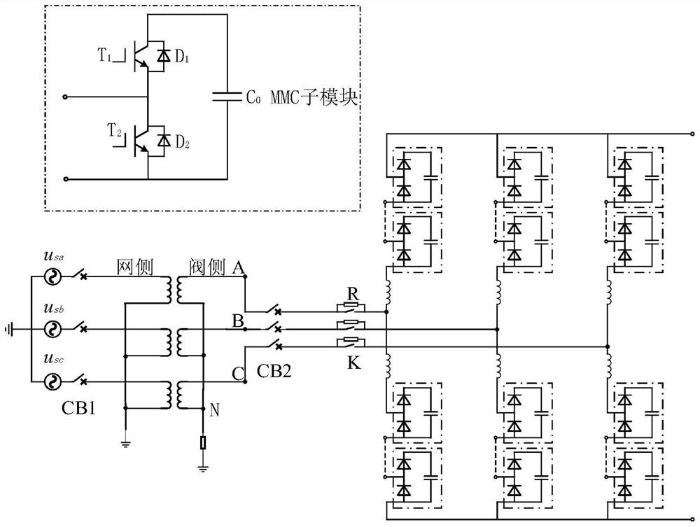
[0026] The present invention provides figure 1 A flexible DC coupling transformer excitation induction is too large, including a coupling transformer, a coupling transformer, a control circuit of the coupling transformer, a circuit breaker, a selective phase housing, including a group, including A, B, and C phase, when connecting the transformer, the MMC is connected, the first phase is B phase, the associated set value of the A, B, and C is α. b = 90 °, α c = 120 ° (240 degrees of B phase), α a = 90 ° (330 degrees of the B phase); when the contact transformer is not connected to the MMC, the first phase is B phase, the a, B, and C phase set value α b = 90 °, α c = 90 °, α a = -90 °.

[0027] When the coupled transformer web side circuit breaker is only b, when the phase B-phase voltage instantaneous value is positive, the B point potential is greater than the N point potential, and the B-phase bridge arm in the MMC is all sub-modules D2 and A, C phase. The bridge arm all sub-modu...

Embodiment 2

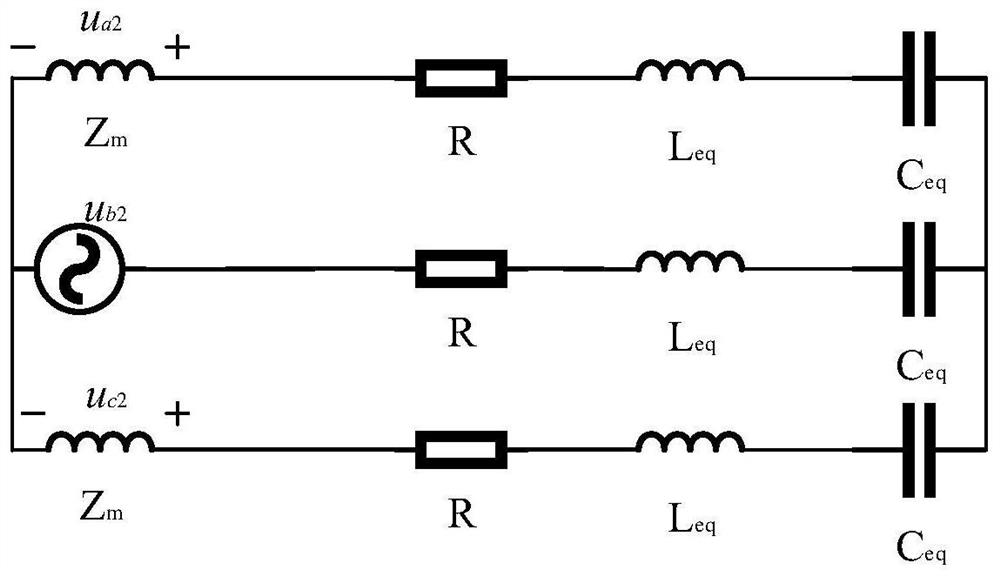
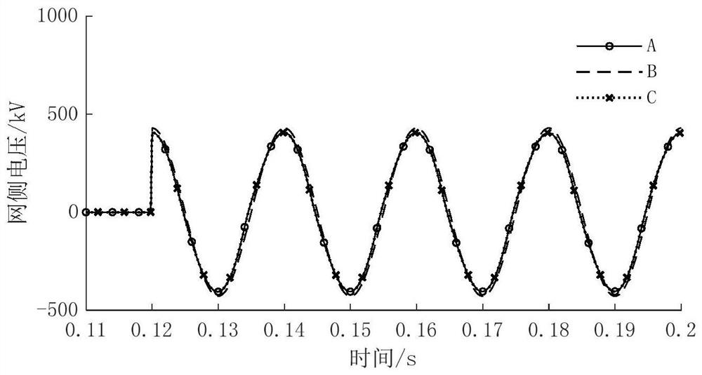
[0035] See Figure 1-6

[0036] An analysis method for exact cause of extension of flexible DC coupling transformers

[0037]In order to suppress the excitation surge flow at the time of charging of the connection transformer in the conversion unit three, the selected phase housing device, selectable, selectable, selectable, and C-phase set value ( Taking a phase-phase voltage reference) is 90 °, 30 °, 150 °, that is, 90 °, -90 °, -90 ° at A, B, and C phase voltage, this value is in accordance with three single-phase transformers When the three-phase transformer composed of the YNYN0 method is calculated, when the selection of the coupling transformer is commissioned, it is debugging when charging the coupling transformer web side in the case of the coupling transformer valve side.

[0038] 1, when the flexible DC valve side belt is charged after the flexible DC valve is charged, the cause analysis of the voltage of A and C after connecting the transformer B together.

[0039] fig...


PUM


Abstract

The invention discloses a solution method for controlling overlarge magnetizing inrush current of a flexible direct-current connection transformer.A connection transformer is included, a phase selection closing device is arranged on a control loop of an incoming circuit breaker of the connection transformer, the phase selection closing device comprises A, B and C phases, when the connection transformer is in no-load closing, an MMC is connected, and when the first closing phase is the B phase, the closing fixed values alpha b of the A phase, the B phase and the C phase are equal to 90 DEG, the alpha c is equal to 120 DEG (240 DEG of the B phase), and the alpha a is equal to 90 DEG (330 DEG of the B phase); and when the connection transformer is not connected with the MMC during no-load closing and the first closing phase is the phase B, the closing fixed values of the phase A, the phase B and the phase C are alpha b = 90 DEG, alpha c = 90 DEG and alpha a = -90 DEG. According to the invention, the charging sequence operation sequence of the flexible valve group is changed, and the optimal closing angle of each phase is 90 DEG of each phase voltage. When the overlarge closing deviation of the circuit breaker is large, relatively large magnetizing inrush current cannot be caused.

Description

Technical field [0001] The present invention belongs to the technical field of coupling transformers, and more particularly to a solution of a flexible DC coupling transformer excitation inheritance. Background technique [0002] The coupling transformer refers to an apparatus connected between the flexible DC substantifier and the AC system to achieve energy and voltage exchange. At present, the situation in reality: When charging the transformer in the Guangxi side, its A-incentive magnetic inrush flow peak reaches 5.046kA, and the Guangxi side network has a large 2 times, 3 harmonics, resulting in parallel to 5713 AC filter L2 reactor The radiant arresser overvoltage is damaged. At the same time, the Guangxi side voltage A, B, and the C phase voltage is reduced to 220kV, 290kV, 275kV, and thereby causing conventional direct flow changing units, which fail to fail; [0003] When the transformer is charged in Yunnan side, its A-incentive magnetic inrush flow peak reaches 6.776kA...

Claims


Application Information

Patent Timeline
Patent Type & Authority Applications(China)
IPC IPC(8): H02H9/02H02J3/36
CPCH02H9/02H02J3/36Y02E60/60
Inventor 杨洁民张彦良彭福琨张杰熊银武钟昆禹
Owner TIANSHENGQIAO BUREAU CSG EHV POWER TRANSMISSION CO
Learn More