Nursing auxiliary device

An auxiliary device and a sling technology, applied in the field of nursing care for the disabled, can solve problems such as complex operation, high cost, and complex structure, and achieve the effect of low cost, simple structure, and improved well-being

Pending Publication Date: 2021-07-30
李崇文
View PDF0 Cites 0 Cited by
  • Summary
  • Abstract
  • Description
  • Claims
  • Application Information

AI Technical Summary

Problems solved by technology

[0003] The existing nursing auxiliary lifting device has complex structure, high cost and complicated operation

Method used


Image

  • Nursing auxiliary device
  • Nursing auxiliary device
  • Nursing auxiliary device

Examples


Embodiment 1

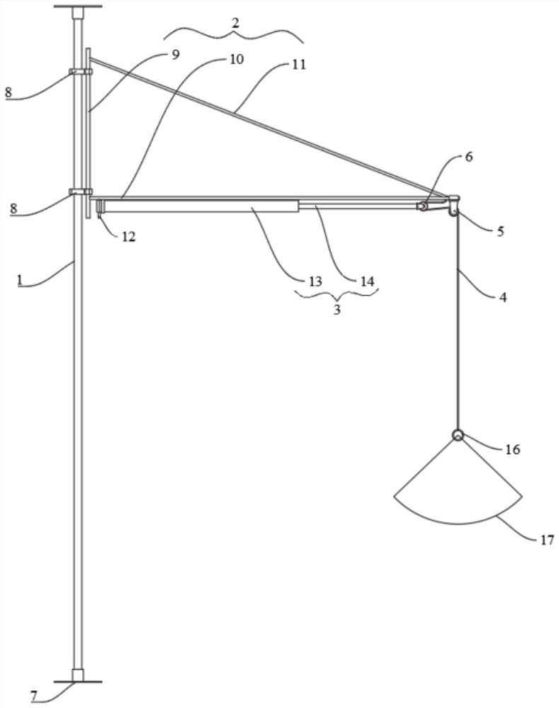
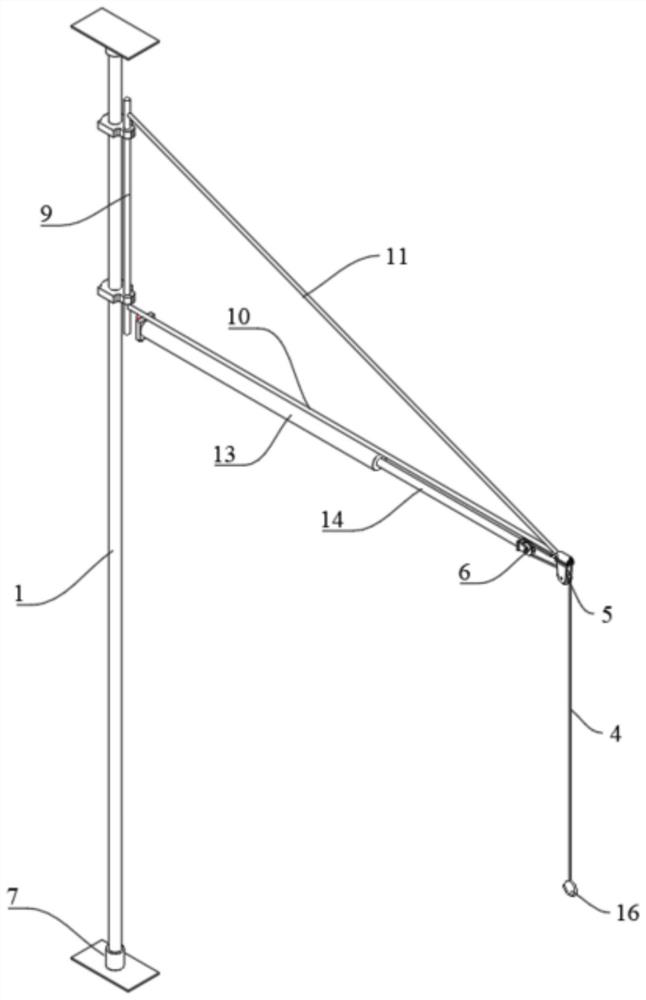
[0032] Such as Figure 1-Figure 2 Shown: a nursing auxiliary device, including a support rod 1, a bracket 2, a push rod 3, a suspension rope 4, a fixed pulley 5, and a movable pulley 6, and the upper and lower ends of the support rod 1 are respectively fixed on the roof by two support seats 7 On the base plate, the upper part of the support rod 1 is provided with two connection seats 8 from top to bottom in sequence, the connection seat 8 is fixedly connected with the support rod 1, and the two connection seats 8 are respectively provided with bearings parallel to the support rod 1, The bracket 2 is flexibly connected with the connecting base 8 through these two bearings.

[0033] The support 2 is in the shape of a right triangle, and what is connected with the connecting seat 8 is the first right-angled side 9, the lower end of the first right-angled side 9 is connected with the left end of the second right-angled side 10, and the upper end of the first right-angled side 9 is...

Embodiment 2

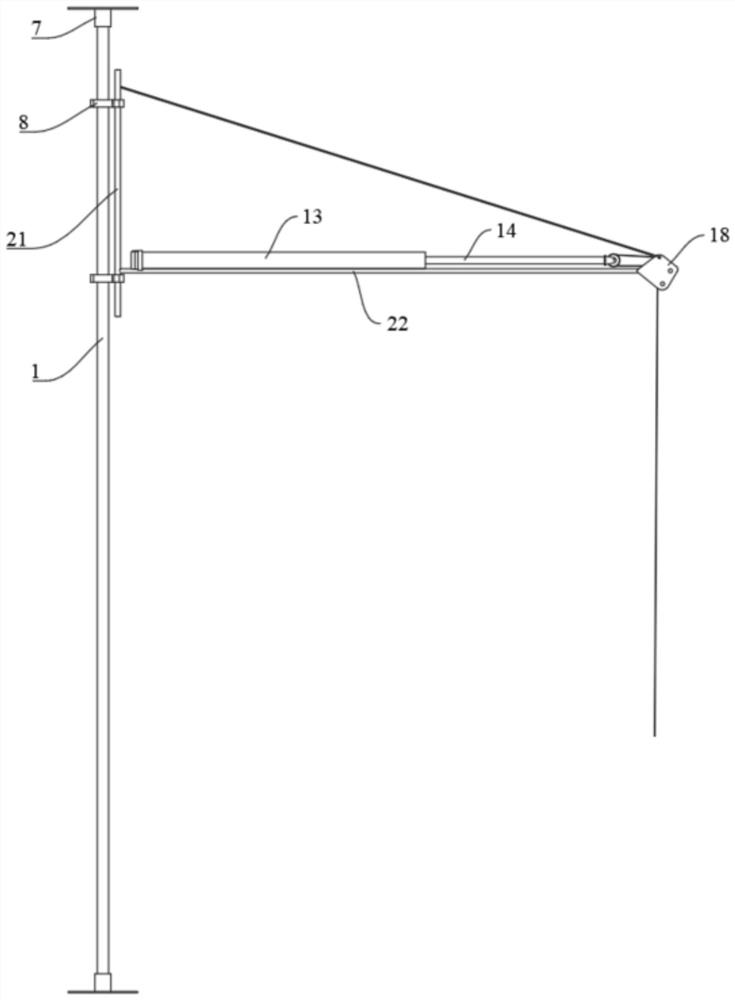
[0038] Such as image 3 , Figure 4 Shown: the general structure of embodiment two is similar to embodiment one, compared with embodiment one, the difference technical feature of embodiment two is as follows:

[0039] The support 2 is L-shaped, the vertical bar 21 of the support 2 is connected with the support bar 1 through the connecting seat 8, the lower end of the vertical bar 21 is fixedly connected with the left end of the cross bar 22, and the right end of the cross bar 22 is provided with a connector 18, the connection Part 18 is two plate surfaces arranged in parallel, and these two plate surfaces are directly welded on the cross bar 22, or welded on a sleeve, and then the sleeve is sleeved on the right end of the cross bar 22, the two The upper part between the boards is provided with a tie bar which is perpendicular to the boards and is fixedly connected with the two boards. Two fixed pulleys 5, wherein one fixed pulley 5 is arranged on the end of cross bar 22, and...

Embodiment 3

[0043] Such as Figure 5 Shown: the general structure of embodiment three is identical with embodiment one or embodiment two, compared with it its difference technical feature is:

[0044] In the wall body of the supporting part of the three embodiments, the fixing seat 20 is set on the wall body through expansion bolts or other methods, and the connecting seat 8 is set on the fixing seat 20 , and then set on the connecting seat 8 .


PUM


Abstract

The invention belongs to the field of disabled person nursing, and particularly relates to a nursing auxiliary device. The device comprises a support, a lifting rope and a push rod, the push rod comprises a base and a rod body, the base is connected with the support, and one end of the rod body is embedded into the base and movably connected with the base; a first pulley is arranged at the other end of the rod body, and a second pulley is arranged on the support; one end of the lifting rope is fixedly connected with the support, the lifting rope, the first pulley and the second pulley form a movable pulley block, and a lifting hook is arranged at the other end of the lifting rope; the device further comprises a lifting mechanism which is connected with the lifting hook; the device further comprises a supporting part which is connected with the support. The auxiliary device is simple in structure and low in cost, and can be conveniently installed in a bedroom or a rehabilitation center at home to assist in lifting and lifting patients or old people needing to be nursed for a long time for baby diaper replacement or defecation treatment and other conventional nursing work.

Description

technical field [0001] The invention belongs to the field of nursing care for disabled persons, and in particular relates to a nursing auxiliary device. Background technique [0002] In the nursing process of the disabled, it is necessary to lift the disabled to facilitate daily care such as scrubbing the body and changing diapers. Therefore need a kind of auxiliary lifting device, the old man who needs nursing or the person who is paralyzed in bed is held up, is convenient to the nursing work of nursing staff. [0003] The existing nursing auxiliary lifting device has complex structure, high cost and complicated operation. Contents of the invention [0004] In order to solve the above problems, the present invention provides a nursing auxiliary device, which is achieved through the following technical solutions: a nursing auxiliary device, including a bracket and a hanging rope, and is characterized in that it also includes a push rod, and the push rod It includes a bas...

Claims


Application Information

Patent Timeline
Patent Type & Authority Applications(China)
IPC IPC(8): A61G7/14
CPCA61G7/1009A61G7/1015A61G7/1025A61G7/1044
Inventor 李崇文
Owner 李崇文
Why Eureka
Try Eureka