In-mold riveting device of stamping mold

An in-mold riveting and stamping die technology is applied in the field of in-mold riveting devices, which can solve the problems that production efficiency and product consistency are difficult to achieve expectations, rivets and main strips are difficult to achieve precise positioning, and the degree of automation is low. The effect of reducing the difficulty of post-maintenance, low replacement maintenance cost, and improving production efficiency and quality stability

Pending Publication Date: 2021-07-30
桂林金格电工电子材料科技有限公司
View PDF5 Cites 0 Cited by
  • Summary
  • Abstract
  • Description
  • Claims
  • Application Information

AI Technical Summary

Problems solved by technology

[0004] 1. The mold is complex and difficult to install, and later maintenance requires mold removal, which is difficult to maintain
[0005] 2. It is difficult to achieve accurate positioning of rivets and main strips
[0006] 3. The degree of automation of processing is not high
[0007] 4. Production efficiency and product consistency are difficult to meet expectations

Method used


Image

  • In-mold riveting device of stamping mold
  • In-mold riveting device of stamping mold
  • In-mold riveting device of stamping mold

Examples


Embodiment Construction

[0032] The technical solutions of the present invention will be further described below in conjunction with the embodiments shown in the accompanying drawings.

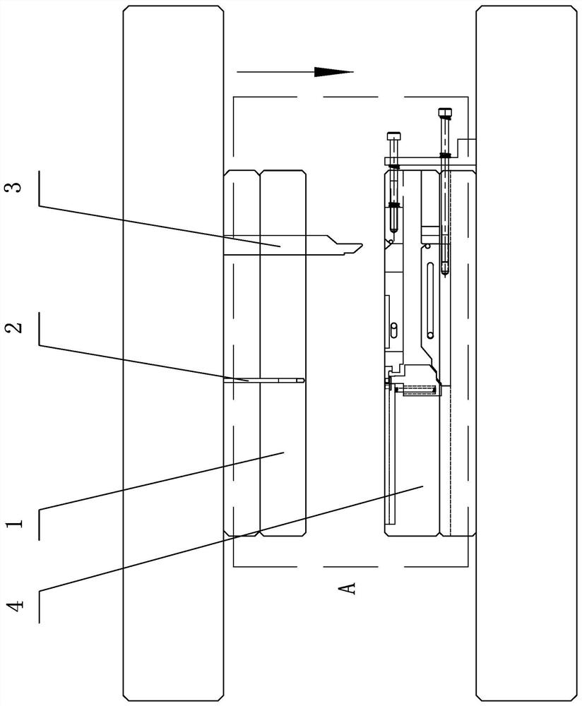
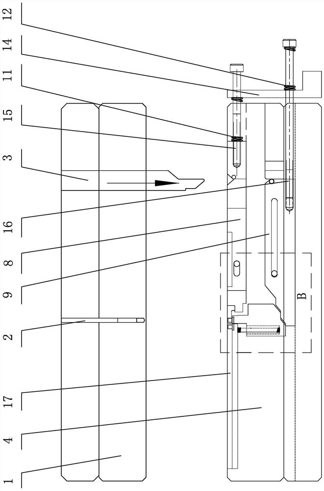
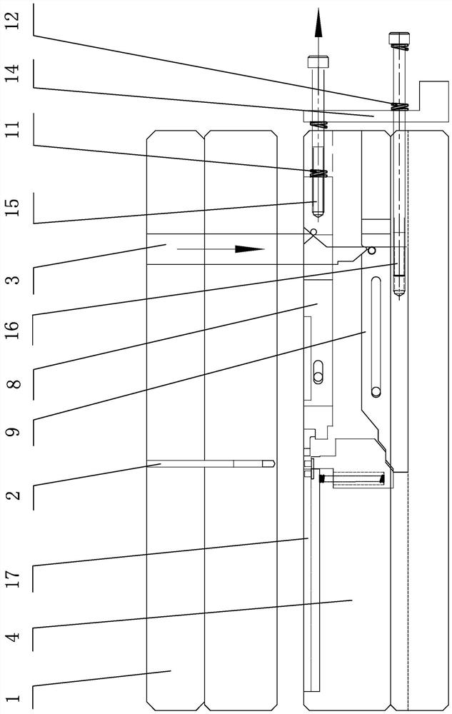
[0033] The in-mold riveting device of the stamping die of the present invention includes an in-mold riveting unit, and the in-mold riveting unit includes a vertical push rod 3 arranged on the upper die body 1 at the front position, and a vertical push rod 3 arranged on the upper die body 1 at the rear position. Punch 2, and the riveting mechanism provided on the lower die body 4, the push rod 3 grows downwards out of the punch 2, and the lower end of the push rod 3 is a push-down wedge 3-1 inclined backward and upward, The rod body of the push rod 3 above the push-down wedge head 3-1 is provided with a push-up wedge surface 3-2 inclined forward and upward, and the position of the push-up wedge surface 3-2 is lower than the punch 2, such as figure 1 , Figure 7 shown.

[0034] The riveting mechanism includes a rivet ...


PUM


Abstract

The invention discloses an in-mold riveting device of a stamping mold. An in-mold riveting unit of the in-mold riveting device comprises a push rod, a punch and a rivet feeding mechanism, wherein the push rod and the punch are arranged on an upper mold body in a front-and-back mode, and the rivet feeding mechanism is arranged on a lower mold body; the rivet feeding mechanism comprises a rivet positioning base and a rivet positioning plate; the rivet positioning base is arranged on a buoyancy lift body capable of sliding up and down and is opposite to the punch; the rivet positioning plate is arranged on the front side of the rivet positioning base and is arranged at the rear end of an upper sliding plate capable of sliding front and back; the bottom of the rivet positioning base is connected with the rear end of a lower sliding plate capable of sliding front and back through a matched slope step; a return spring I for resetting the buoyancy lift body downwards, a return spring II for resetting the upper sliding plate backwards and a return spring III for resetting the lower sliding plate forwards are arranged; a lower push wedge head obliquely arranged towards the upper rear portion is arranged at the lower end of the push rod; an upper push wedge face obliquely arranged towards the upper front portion is arranged on the push rod; an upper push wedge groove aligned and matched with the upper push wedge face is formed in the upper sliding plate at the reset position; and a lower push wedge groove aligned and matched with the lower push wedge head is formed in the lower sliding plate.

Description

technical field [0001] The invention relates to a stamping die structure, in particular to an in-mold riveting device for a stamping die. Background technique [0002] In order to improve the production efficiency and product quality of hardware, in the existing technology, there is a patented technology that combines the two processes of stamping and riveting into one in the stamping die, such as ① the publication number is CN109848357A "Riveting Stamping Machine Die" Application for Invention of Inner Riveting Mold, ② Application for Invention of "Automatic Feeding Mechanism for In-mold Riveting" with publication number CN104690208B, ③ Application for Invention of "Multi-station Riveting Multi-station Progressive Mold with Contact Front in Mold" with publication number CN104759534A, ④ Publication No. It is CN106975697A's "in-mold automatic riveting molding die for riveting contact point" invention application, and ⑤ publication number is CN103406444A's "notebook cooling fi...

Claims


Application Information

Patent Timeline
Patent Type & Authority Applications(China)
IPC IPC(8): B21J15/32B21J15/16B21J15/44
CPCB21J15/16B21J15/32B21J15/44
Inventor 覃绍培厉嘉平何宽顺
Owner 桂林金格电工电子材料科技有限公司
Why Eureka
Try Eureka