
Planetary plate clamp, technology for machining rhombic blade through planetary plate clamp and rhombic blade

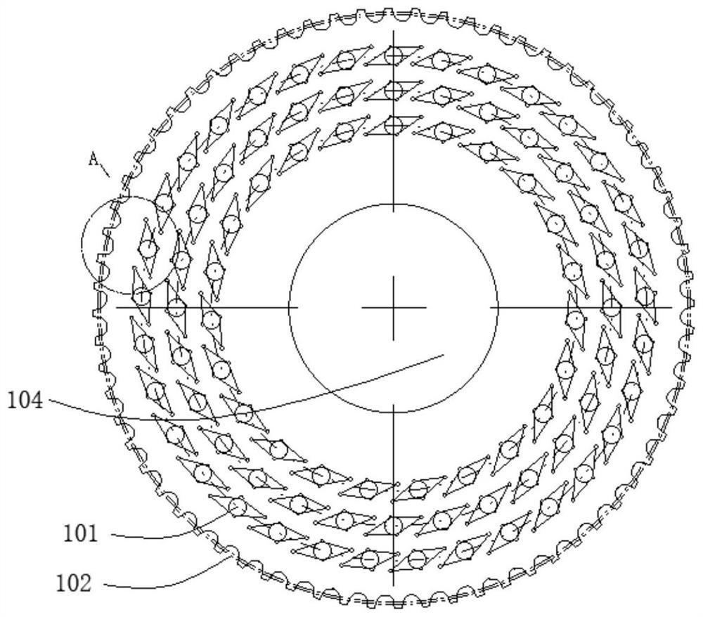
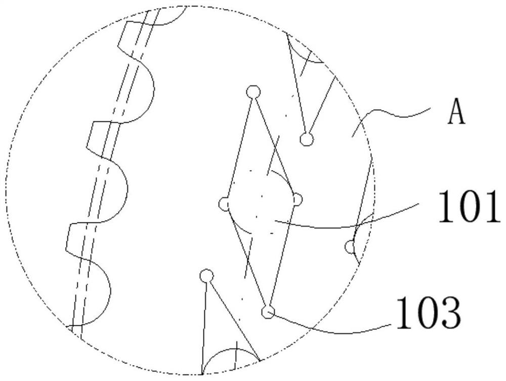
A planetary disc and fixture technology, which is applied in the direction of manufacturing tools, grinding workpiece supports, and other manufacturing equipment/tools, can solve the problems of uneven density distribution, large deformation of the bottom surface, and high scrap rate, so as to avoid rapid wear and tear. Larger, eliminates grinding errors, and improves service life

Active Publication Date: 2021-07-30
JIANGXI RARE EARTH & RARE METALS TUNGSTEN GRP HLDG CO LTD +2
View PDF16 Cites 1 Cited by
  • Summary
  • Abstract
  • Description
  • Claims
  • Application Information

AI Technical Summary

Problems solved by technology

[0002] VCGX series aluminum blades are 35-degree diamond-shaped blades. Because of the large counterbore, the two blade tips are higher than the middle part, and the drop is more than 0.5mm. The density distribution after pressing is seriously uneven, and the deformation of the blank after sintering is very large. The flatness of the bottom surface is more than 0.3mm. When grinding the bottom surface, use the pressure plate to press the two knife tips and install it in the planetary disc for grinding. Due to the large deformation of the bottom surface, the two knife tips of the product at an angle of 145° after grinding out The height will be seriously out of tolerance and the scrap rate will be high
Pass rate below 80%

Method used


Image

  • Planetary plate clamp, technology for machining rhombic blade through planetary plate clamp and rhombic blade
  • Planetary plate clamp, technology for machining rhombic blade through planetary plate clamp and rhombic blade
  • Planetary plate clamp, technology for machining rhombic blade through planetary plate clamp and rhombic blade

Examples


Embodiment 1

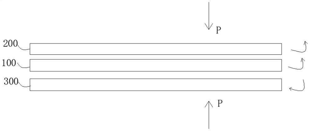
[0043] The above-mentioned processing technology is used, the difference is that the pressure is 5 pressure sections, and the specific P0 is 90N pressure and standing for 4s;

[0044] P1 is under 226N pressure, the upper grinding disc rotates 45rpm forward, the planetary disc fixture rotates 30rpm forward, and the lower grinding disc reverses 45rpm, and the time is 5s;

[0045] P2 is under the pressure of 470N, the upper grinding disc rotates forward at 70rpm for 8s, the planetary disc fixture rotates forward at 40rpm for 5s, and the lower grinding disc reverses at 90rpm for 8s;

[0046] P3 is under the pressure of 780N, the upper grinding disc rotates forward at 80rpm for 8s, the planetary disc fixture rotates forward at 50rpm for 5s, and the lower grinding disc reverses at 110rpm for 8s;

[0047] P4 is under 320N pressure, the upper grinding disc rotates 30rpm forward, the planetary disc fixture rotates 25rpm forward, and the lower grinding disc reverses 30rpm, and the time ...

Embodiment 2

[0050] The above-mentioned processing technology is used, the difference is that the pressure is 5 pressure sections, and the specific P0 is 120N pressure and standing for 5s;

[0051] P1 is under 280N pressure, the upper grinding disc rotates 45rpm forward, the planetary disc fixture rotates 30rpm forward, and the lower grinding disc reverses 45rpm, and the time is 5s;

[0052] P2 is under the pressure of 490N, the upper grinding disc rotates forward at 70rpm for 8s, the planetary disc fixture rotates forward at 40rpm for 5s, and the lower grinding disc reverses at 90rpm for 8s;

[0053] P3 is under the pressure of 730N, the upper grinding disc rotates forward at 80rpm for 8s, the planetary disc fixture rotates forward at 50rpm for 5s, and the lower grinding disc reverses at 110rpm for 8s;

[0054] P4 is under the pressure of 250N, the upper grinding disc rotates 30rpm forward, the planetary disc fixture rotates 25rpm forward, and the lower grinding disc reverses 30rpm, and the...

Embodiment 3

[0057] The above processing technology is used, the difference is that the pressure is 5 pressure sections, and the specific P0 is 130N pressure and standing for 3s;

[0058] P1 is under 240N pressure, the upper grinding disc rotates 45rpm forward, the planetary disc fixture rotates 30rpm forward, the lower grinding disc reverses 45rpm, and the time is 5s;

[0059] P2 is under the pressure of 470N, the upper grinding disc rotates forward at 70rpm for 8s, the planetary disc fixture rotates forward at 40rpm for 5s, and the lower grinding disc reverses at 90rpm for 8s;

[0060] P3 is under the pressure of 790N, the upper grinding disc rotates forward at 80rpm for 8s, the planetary disc fixture rotates forward at 50rpm for 5s, and the lower grinding disc reverses at 110rpm for 8s;

[0061] P4 is under 340N pressure, the upper grinding disc rotates 30rpm forward, the planetary disc fixture rotates 25rpm forward, and the lower grinding disc reverses 30rpm, and the time is 5s;

[00...


PUM


Abstract

The invention discloses a planetary plate clamp, a technology for machining a rhombic blade through the planetary plate clamp and the rhombic blade, and belongs to the field of hard alloy blades. The planetary plate clamp comprises a clamp body which is provided with a receding hole and a plurality of workpiece placing positions, and the workpiece placing positions are annularly arranged along the receding hole; and each workpiece placing position comprises a placing cavity and an avoiding hole, and a gap between the placing cavity and a machined part placed in the placing cavity is smaller than or equal to 0.1 mm. According to the planetary plate clamp, the gap between the placing cavity and the machined part placed in the placing cavity is controlled to be smaller than or equal to 0.1 mm, it can be guaranteed that the periphery of the workpiece and two acute-angle tool noses are positioned at the same time during grinding, and grinding errors caused by the fact that the planeness of the bottom face is out of tolerance are eliminated.

Description

technical field [0001] The invention relates to the field of cemented carbide cutting tools, in particular to a planetary disk fixture, a process for processing diamond-shaped blades by using the same, and a diamond-shaped blade. Background technique [0002] VCGX series aluminum blades are 35-degree diamond-shaped blades. Because of the large counterbore, the two blade tips are higher than the middle part, and the drop is more than 0.5mm. The density distribution after pressing is seriously uneven, and the deformation of the blank after sintering is very large. The flatness of the bottom surface is more than 0.3mm. When grinding the bottom surface, use the pressure plate to press the two knife tips and install it in the planetary disc for grinding. Due to the large deformation of the bottom surface, the two knife tips of the product at an angle of 145° after grinding out The height will be seriously out of tolerance and the scrap rate will be high. The passing rate is less...

Claims


Application Information

Patent Timeline
Patent Type & Authority Applications(China)
IPC IPC(8): B24B41/06B24B3/36B24B1/00
CPCB24B41/06B24B3/36B24B1/00
Inventor 谢小乾罗强梁瑜舒淑珍刘恒嵩陈玉柏覃伟坚鄢志刚
Owner JIANGXI RARE EARTH & RARE METALS TUNGSTEN GRP HLDG CO LTD
Learn More