Real-time monitoring terminal for industrial boiler

A technology for real-time monitoring and industrial boilers, applied in the direction of controlling combustion, combustion methods, combustion chambers, etc., can solve the problems of small real-time monitoring terminal force, inconvenient use of industrial boilers, and inability to adjust boilers, etc., to achieve intelligent control and convenience The effect of operation and avoiding waste of heat

Inactive Publication Date: 2021-07-30
冯爱红
View PDF5 Cites 0 Cited by
  • Summary
  • Abstract
  • Description
  • Claims
  • Application Information

AI Technical Summary

Problems solved by technology

[0005] Aiming at the deficiencies of the prior art, the present invention provides a real-time monitoring terminal for industrial boilers, mainly to solve the problem that when using industrial boilers, the boiler cannot be adjusted in time according to the monitoring, resulting in too small force of the real-time monitoring terminal, which is inconvenient Problems with the use of industrial boilers

Method used


Image

  • Real-time monitoring terminal for industrial boiler
  • Real-time monitoring terminal for industrial boiler
  • Real-time monitoring terminal for industrial boiler

Examples


Embodiment 1

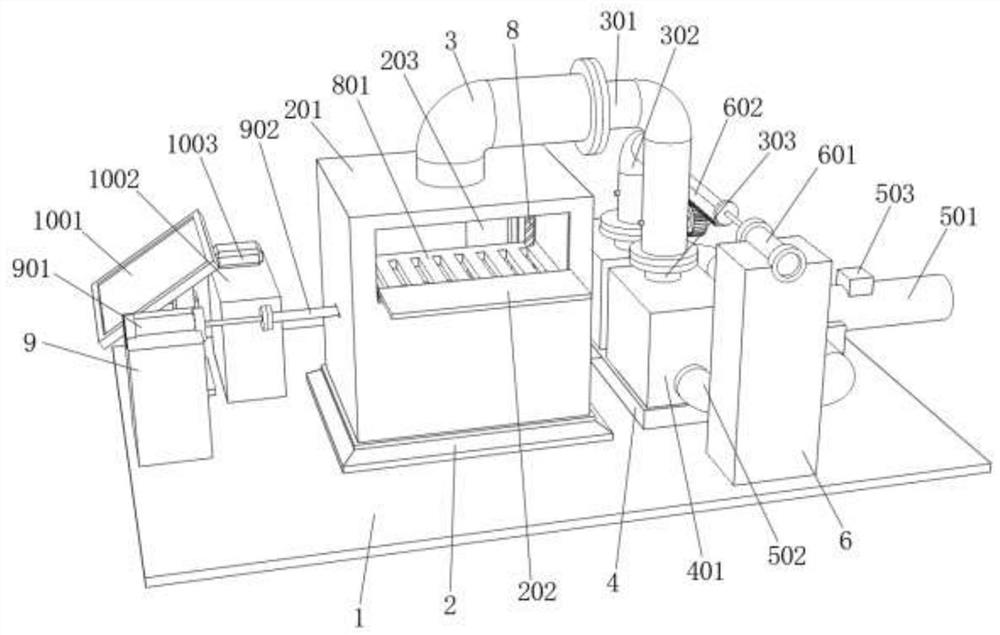
[0036] refer to Figure 1-Figure 5 , an industrial boiler real-time monitoring terminal, comprising a base plate 1, the upper surface of the base plate 1 is fixed with a heat-insulating base 2 by bolts, the upper surface of the heat-insulating base 2 is fixed with a boiler body 201 by bolts, and the outer walls of both sides of the boiler body 201 are provided with seals The first sealing plate 202 and the second sealing plate 203 are connected to one side of the two sealing ports respectively, and the top of the inner wall of the boiler body 201 is provided with a temperature sensor 204, wherein the model of the temperature sensor 294 is ATS1-82, and the temperature sensor 204 cooperates with the control mechanism, so that the controller 1004 can monitor the temperature in the boiler body 201 in real time through the temperature sensor 204, wherein the model of the controller 1004 is DATA-7311, and the bottom of the inner wall of the boiler body 201 is welded with multiple gui...

Embodiment 2

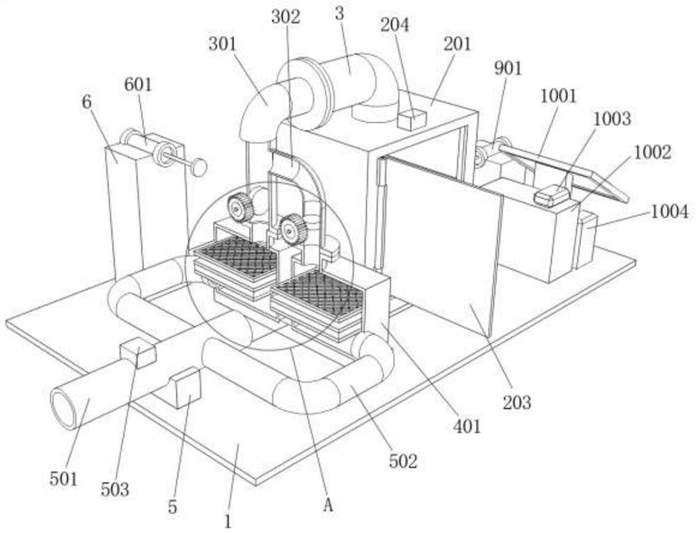
[0040] refer to Figure 6-Figure 7, the upper surface of the fixed block 1002 is fixed with a mobile hard disk 11 by bolts, the upper surface of the boiler body 201 is fixed with an installation block 1101 by bolts, the upper surface of the installation block 1101 is fixed with a speaker 1102 and a flashing light 1103 by bolts, and the mobile hard disk 11, speaker 1102 The speaker 1102 and the flashing light 1103 are electrically connected to the output terminal of the controller 1004, and the speaker 1102 and the flashing light 1103 cooperate to form a warning mechanism. Warning, convenient for nearby workers to check the boiler in time, repair and maintain it, and avoid damage to the boiler. The top of the inner wall of the boiler body 201 is fixed with a protective net 1104 by bolts, and the protective net 1104 is located at the bottom of the installation port of the boiler body 201 The protective net 1104 intercepts the solid matter in the combustion fuel, fully burns it, ...


PUM


Abstract

The invention relates to the technical field of industrial boilers, and discloses a real-time monitoring terminal for an industrial boiler. The real-time monitoring terminal comprises a bottom plate, a heat insulation base is fixedly connected to the upper surface of the bottom plate, a boiler body is fixedly connected to the upper surface of the heat insulation base, sealing openings are formed in the outer walls of the two sides of the boiler body, a first sealing plate and a second sealing plate are rotationally connected to one side of the two sealing openings respectively, a temperature sensor is arranged at the top of the inner wall of the boiler body, a plurality of guide rods are fixedly connected to the bottom of the inner wall of the boiler body, and the same hollowed-out plate is movably connected to one sides of the circumferences of the guide rods. The temperature in the boiler body can be monitored in real time, a second electric telescopic rod is matched with a movable mechanism and a concave-convex block to move the hollowed-out plate up and down, ash on the hollowed-out plate is separated from fuel, sufficient combustion of the fuel is guaranteed, a controller controls a valve actuator to close a ventilation opening of the device, and the fuel in the boiler body is extinguished, so that heat waste caused by excessive combustion of the fuel is avoided.

Description

technical field [0001] The invention relates to the technical field of industrial boilers, in particular to a real-time monitoring terminal for industrial boilers. Background technique [0002] Industrial boilers are thermal equipment commonly used in various fields of society in our country. According to their uses, industrial boilers are divided into industrial parks, residential areas, enterprises, hotels, etc. for central heating and heating; according to fuel, industrial boilers are divided into fuel oil and gas , coal, biomass, waste incinerators, etc. The number of industrial boilers is large, the average capacity of a single unit is low, the operating efficiency is generally low, the operating cost is high, the emission is not up to standard, the safety problems occur frequently, and the faults cannot be solved in time. With the rapid development of Internet technology and the national intelligent manufacturing, Due to the influence of traditional industrial promoti...

Claims


Application Information

Patent Timeline
Patent Type & Authority Applications(China)
IPC IPC(8): F23M11/04F23N5/00
CPCF23M11/04F23N5/00F23N2231/22
Inventor 冯爱红
Owner 冯爱红
Why Eureka
Try Eureka