Calibration system and measurement method thereof

A calibration system and measurement method technology, applied in the field of precision measurement instruments, can solve problems such as low efficiency, inability to obtain included angle data, and difficulty in achieving ideal results, and achieve the effect of improving efficiency and improving measurement accuracy.

Active Publication Date: 2021-07-30
CHOTEST TECH INC
View PDF8 Cites 1 Cited by
  • Summary
  • Abstract
  • Description
  • Claims
  • Application Information

AI Technical Summary

Problems solved by technology

[0005]1) After adjustment, no clear angle data can be obtained, so it is difficult to perform high-precision compensation
[0006]2) Since the fixture data cannot be obtained, it is necessary to adjust the parallelism to an ideal level as much as possible, and repeated adjustments are required, which is inefficient and difficult to achieve the ideal level Effect;

Method used


Image

  • Calibration system and measurement method thereof
  • Calibration system and measurement method thereof
  • Calibration system and measurement method thereof

Examples


Embodiment Construction

[0029] The present invention will be further described below with reference to the accompanying drawings and specific embodiments.

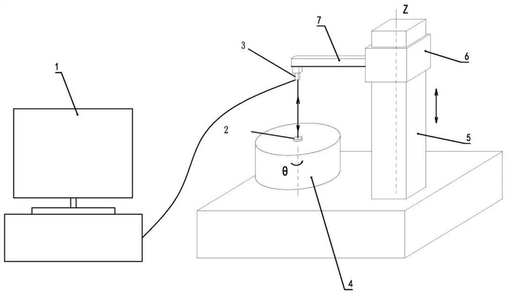
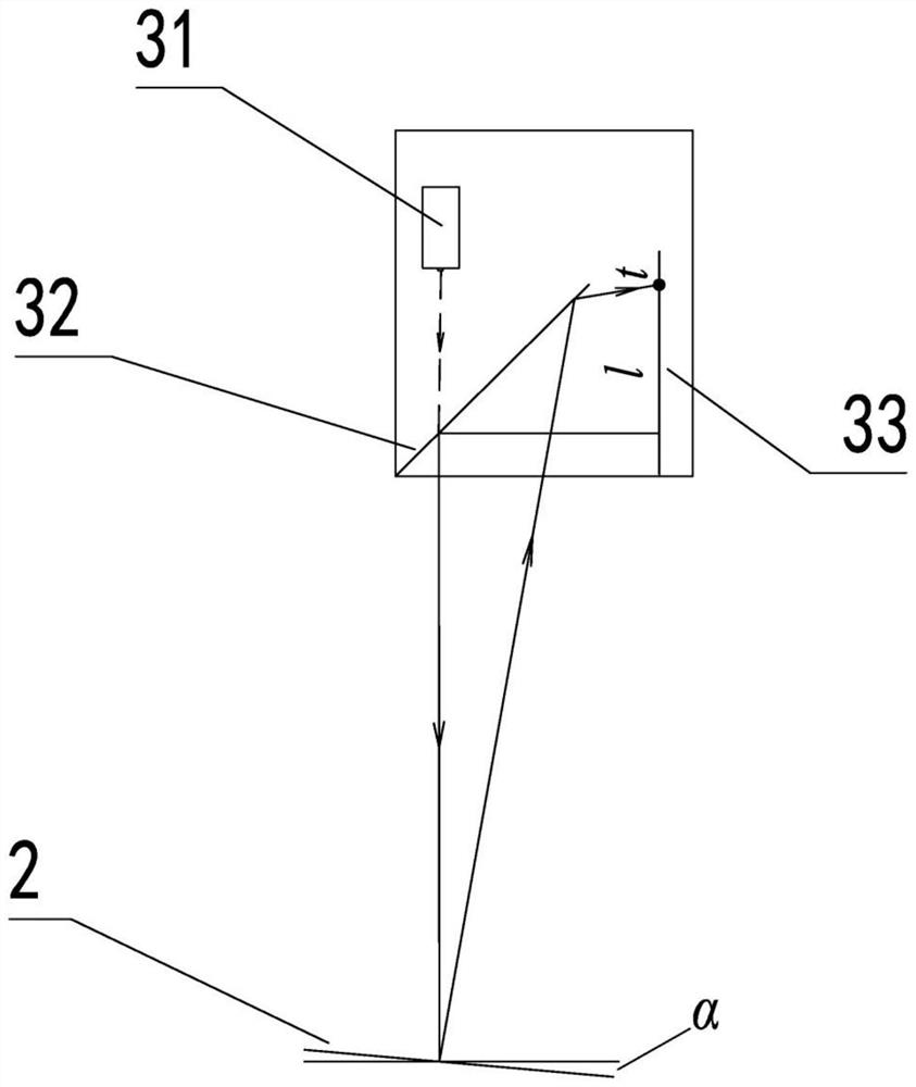
[0030] like Figure 2 to Figure 5 As shown, a calibration system includes three parts, an optical transmitting and receiving device 3, a mirror 2 and a computing unit 3, which work together to realize the acquisition of the included angle.

[0031] Based on this calibration system, the following measurement method of the calibration system is carried out to measure the angle between the movement axis of the guide rail 5 and the rotation axis of the turntable 4:

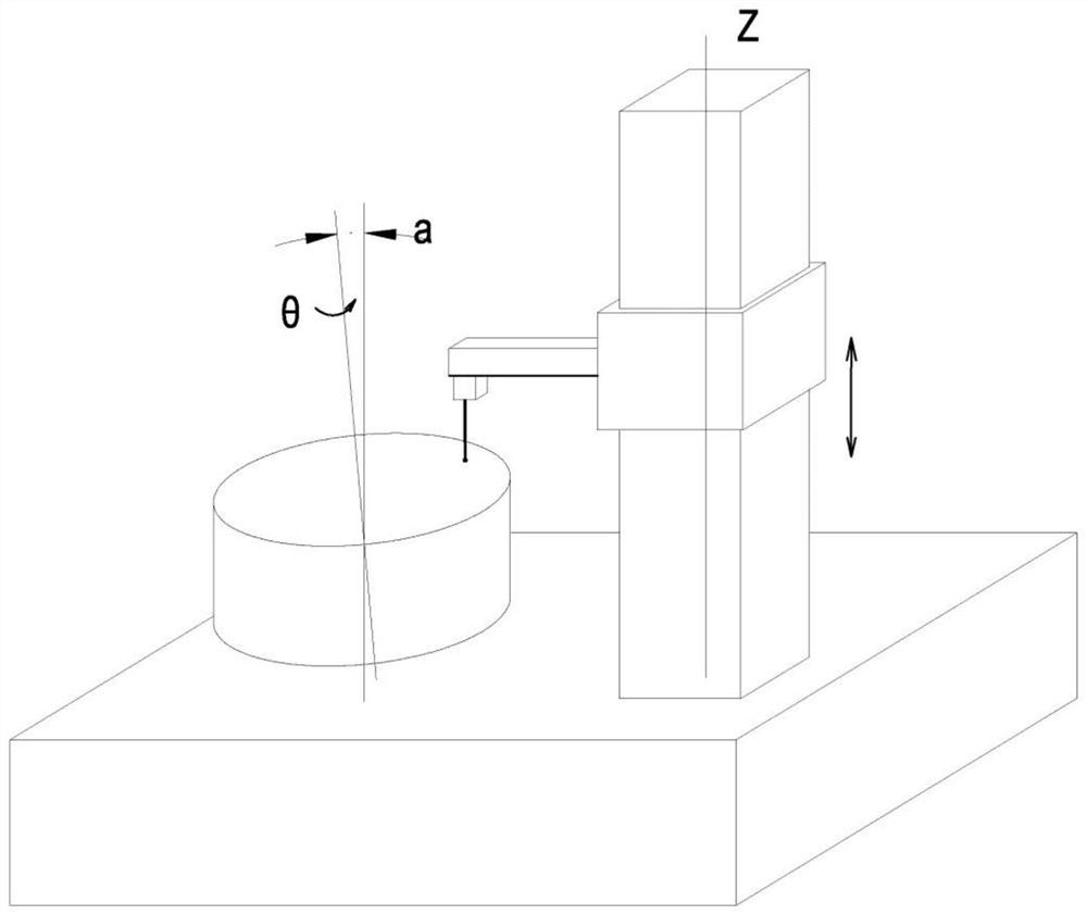
[0032] The reflector 2 is arranged on the turntable 4, the optical transmitting and receiving device 3 is arranged on the guide rail slider 6 through the beam 7, the guide rail slider 6 is installed on the guide rail 5, the guide rail 5 is a Z-axis guide rail, the turntable 4 is rotated, and the light spot A circle is drawn on the mirror 2, and the position of the mirror 2 is adjusted t...


PUM


Abstract

The invention provides a calibration system which comprises a calculation unit, an optical transmitting and receiving device, a reflector, a rotary table and a guide rail, wherein the reflector is installed in the center of the rotary table, the guide rail is connected with a guide rail sliding block, the optical transmitting and receiving device is installed on the guide rail sliding block, the optical transmitting and receiving device is suspended right above the reflector, and the optical transmitting and receiving device is connected with the computing unit. The invention also provides a measurement method of the calibration system. The system has the beneficial effect that the included angle data of the guide rail moving shaft and the rotary table rotating shaft can be accurately collected.

Description

technical field [0001] The invention relates to a precision measuring instrument, in particular to a calibration system and a measurement method of the calibration system. Background technique [0002] In precision measuring instruments, especially in the cylindrical coordinate measuring system, it is often required that the guide rail movement axis Z is parallel to the turntable rotation axis θ, such as figure 1 In order to form an ideal cylindrical coordinate system to achieve precise measurement. But in fact, no matter how it is adjusted, there must be a space angle α between the motion axis of the guide rail and the rotation axis of the turntable. Since the two axes are virtual, this angle cannot be accurately measured or compensated. [0003] The existing traditional practice is to use the standard cylinder to adjust, through repeated adjustment, make the center of the standard cylinder pass the axis of the turntable, and then use the standard cylinder as the benchmark...

Claims


Application Information

Patent Timeline
Patent Type & Authority Applications(China)
IPC IPC(8): G01B21/00G01B11/26
CPCG01B21/00G01B11/26
Inventor 张鹏肖田
Owner CHOTEST TECH INC
Why Eureka
Try Eureka