Precision detection device for optical fiber gyroscope production

A fiber optic gyroscope and precision detection technology, applied in the field of fiber optic gyroscopes, can solve the problems of detection data deviation, gyroscope axis deviation, large fixed arc plate, etc.

Inactive Publication Date: 2021-07-30
刘铭
View PDF1 Cites 0 Cited by
  • Summary
  • Abstract
  • Description
  • Claims
  • Application Information

AI Technical Summary

Problems solved by technology

The above-mentioned patents have the following disadvantages: when the above-mentioned device is fixed to the gyroscope, the fixing screws need to be tightened from three directions. Once one of the fixing screws is not screwed in place, the relative gap between the positions of the fixing arc plates is too large, which may easily cause the axis of the gyroscope to deviate. , resulting in deviations in the final detection data

Method used


Image

  • Precision detection device for optical fiber gyroscope production
  • Precision detection device for optical fiber gyroscope production
  • Precision detection device for optical fiber gyroscope production

Examples


Embodiment 1

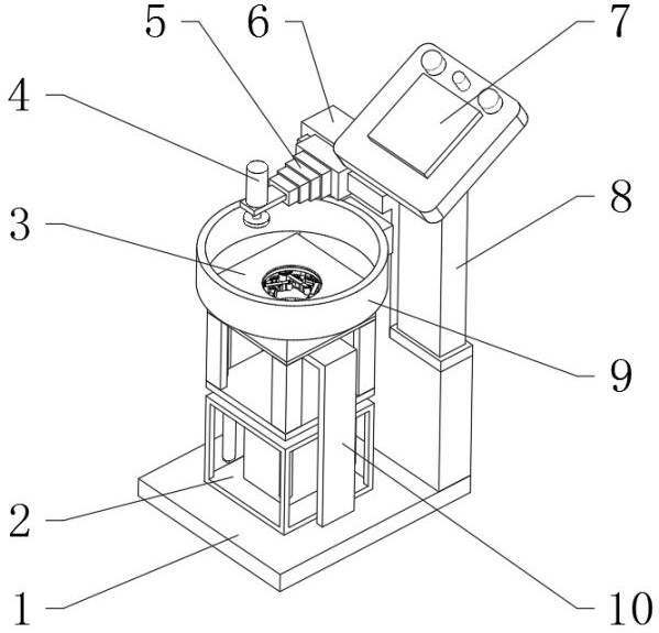
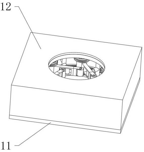
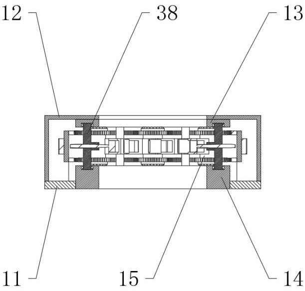
[0035] A fiber optic gyroscope production accuracy detection device, such as Figure 1-8As shown, it includes a bottom plate 1, the top outer wall of the bottom plate 1 is fixedly connected with an adjustment assembly 2, and the top outer wall of the adjustment assembly 2 is fixedly connected with a locking assembly 3; the locking assembly 3 includes an connecting plate 11 and an end frame 22, and the connecting plate 11 The outer wall of the top is fixedly connected with the cover shell 12, the inner wall of the top of the cover shell 12 is fixedly connected with the upper ring 13, the inner wall of the center of the connecting plate 11 is welded with the lower ring 14, the inner walls of the upper ring 13 and the lower ring 14 are both provided with through grooves, and the upper ring The outer wall of the bottom of 13 and the outer wall of the top of lower ring 14 are fixedly connected with six fixed shafts 16 arranged in circumferential disks. The outer wall of the fixed sh...

Embodiment 2

[0041] A kind of precision detection device for fiber optic gyroscope production, this detection device is the precision detection device described in embodiment 1, such as figure 1 As shown, the top outer wall of the bottom plate 1 is fixedly connected with a bracket 10 and a stand 6, a balance platform is arranged on the outer wall of the top center of the bracket 10, the balance platform is coaxial with the upper ring 13, and a slide rail is arranged on the outer wall of one side of the stand 6 , the outer wall of the slide rail is slidably connected with a mobile frame, the outer wall of one side of the mobile frame is provided with a telescopic box 5, the outer wall of one side of the telescopic box 5 is provided with a screw-in unit 4, the outer wall of the bottom of the screw-in unit 4 is provided with a friction turntable, and the outer wall of the top of the stand 6 A control box 8 is provided, the top outer wall of the control box 8 is provided with an operation panel...


PUM


Abstract

The invention discloses a precision detection device for optical fiber gyroscope production, and relates to the technical field of optical fiber gyroscopes. The problem of axis deviation of an existing detection device is solved. The precision detection device specifically comprises a bottom plate, the outer wall of the top of the bottom plate is fixedly connected with an adjusting assembly, the outer wall of the top of the adjusting assembly is fixedly connected with a locking assembly, the locking assembly comprises a connecting plate and an end frame, the outer wall of the top of the connecting plate is fixedly connected with a cover shell, and the inner wall of the top of the cover shell is fixedly connected with an upper ring. By arranging the locking assembly, a power motor is started to drive an outer gear to rotate, the outer gear is meshed with an outer rack to drive a lantern ring to rotate, then an inner rack is meshed with an inner gear to drive a rotary drum to rotate, and a rotary arm rotates, so that a roller on the inner wall of an end frame is gradually tightened; at the moment, the optical fiber gyroscope is placed in the center area of the locking assembly, and the four power motors synchronously work, so that the roller can be uniformly tightened, and the axis of the gyroscope is prevented from deviating.

Description

technical field [0001] The invention relates to the technical field of fiber optic gyroscopes, in particular to a precision detection device for production of fiber optic gyroscopes. Background technique [0002] The existing precision detection device for the production of fiber optic gyroscopes has the problem of firm fixation when fixing the product. Due to the ring design of the fiber optic gyroscope itself, if the axis of the gyroscope cannot be effectively fixed when clamping the outer wall, follow-up When optical fiber deviation is detected, it is easy to cause inaccurate data, so it is necessary to optimize the design of the fixed components of the existing precision detection device. [0003] After searching, the Chinese patent application number is CN201911267646.5, which discloses a detection device for fiber optic gyroscope production, including a host platform, and a horizontal installation groove is opened in the middle of the top of the host platform, and the ...

Claims


Application Information

Patent Timeline
Patent Type & Authority Applications(China)
IPC IPC(8): G01C19/72
CPCG01C19/72
Inventor 刘铭
Owner 刘铭
Why Eureka
Try Eureka