Combined injection mold and working method thereof

An injection mold and combined technology, applied in the field of combined injection molds, can solve the problems of not easy to take out products, low efficiency of manual return, increase manufacturing cost, etc., to achieve convenient and fast production and assembly, reduce the risk of injury, and reduce assembly. effect of time

Pending Publication Date: 2021-08-03
吴伟
View PDF7 Cites 2 Cited by
  • Summary
  • Abstract
  • Description
  • Claims
  • Application Information

AI Technical Summary

Problems solved by technology

[0003] At present, the injection molds in the market require workers to manually extend into the mold to take out the injection molded products after the mold is divided. At this time, the temperature of the newly formed products is still high. Another mold clamping accident may cause safety accidents, and the efficiency of manual material return is low. If an automatic material return device is installed, it is necessary to set up a separate driving component for the material return device, which not only increases the volume of the equipment, but also increases the manufacturing cost of the equipment. ; In addition, in the existing injection mold, the product is easy to stick to the concave mold during the molding process, and the product is not easy to take out after processing; and the existing injection mold, the concave mold and the lower mold base are all integrally formed. After wear and tear, the entire lower mold needs to be replaced, which also indirectly increases the manufacturing cost; therefore, a combined injection mold and its working method are proposed to solve the above-mentioned problems

Method used


Image

  • Combined injection mold and working method thereof
  • Combined injection mold and working method thereof
  • Combined injection mold and working method thereof

Examples


Embodiment Construction

[0036] The following will clearly and completely describe the technical solutions in the embodiments of the present invention with reference to the accompanying drawings in the embodiments of the present invention. Obviously, the described embodiments are only some, not all, embodiments of the present invention. Based on the embodiments of the present invention, all other embodiments obtained by persons of ordinary skill in the art without making creative efforts belong to the protection scope of the present invention.

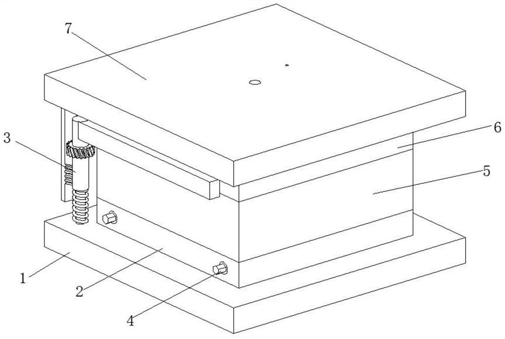
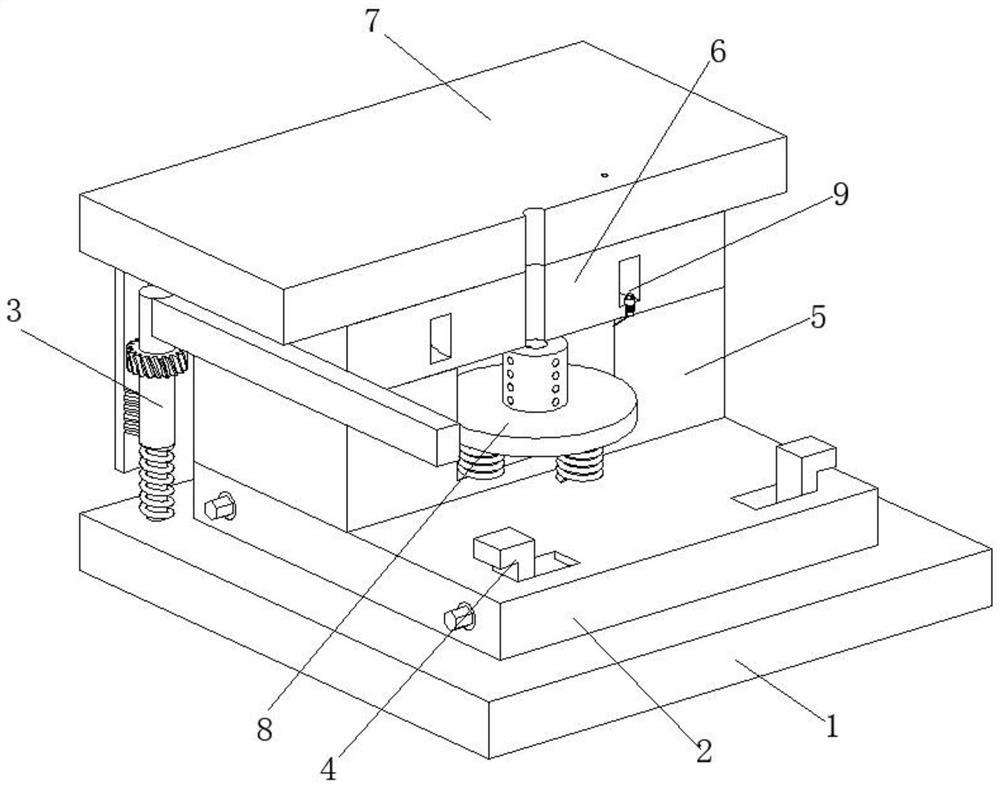
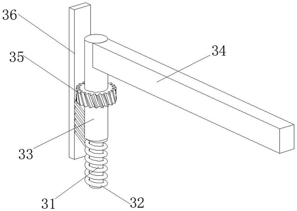
[0037] A combined injection mold and working method thereof, such as Figure 1-Figure 5As shown, the lower mold base 1 is included, the top of the lower mold base 1 is movably connected with a fixed plate 2, the top of the lower mold base 1 is provided with a material return mechanism 3, and the material return mechanism 3 is located at the front of the fixed plate 2, and the fixed plate 2 is provided with a fixing mechanism 4, the top of the fixed plate 2 is ...


PUM


Abstract

The invention relates to the technical field of injection molds, and discloses a combined injection mold and a working method thereof. The combined injection mold comprises a lower mold base, a fixing plate is movably connected to the top of the lower mold base, a material returning mechanism is arranged at the top of the lower mold base, and the material returning mechanism is located at the front portion of the fixing plate; a fixing mechanism is arranged in the fixing plate, a female mold is movably connected to the top of the fixing plate, a male mold is movably connected to the top of the female mold, and an upper mold base is connected to the top of the male mold through bolts; and a discharging mechanism is arranged in the female mold, and a protection mechanism is arranged in the male mold. According to the combined injection mold and the working method thereof, the material returning mechanism can automatically return materials of discharged products after the mold is split through the operation of the material returning mechanism, so that manual material returning by workers is not needed, the contact between the workers and the products is reduced, the risk of injury is reduced, the working efficiency is improved, and the labor intensity of the workers is reduced.

Description

technical field [0001] The invention relates to the technical field of injection molds, in particular to a combined injection mold and a working method thereof. Background technique [0002] Injection molding is a tool for producing plastic products; it is also a tool for giving plastic products a complete structure and precise dimensions. Injection molding is a processing method used in mass production of certain complex-shaped parts. The injection molding machine is injected into the mold cavity under high pressure, and after cooling and solidification, the molded product is obtained. The injection mold is divided into thermosetting plastic mold and thermoplastic plastic mold according to the molding characteristics; according to the molding process, it is divided into transfer mold, blow mold, and cast mold. , thermoforming mold, hot compression mold (compression plastic mold), injection mold, etc. The hot compression mold can be divided into three types: overflow type, s...

Claims


Application Information

Patent Timeline
Patent Type & Authority Applications(China)
IPC IPC(8): B29C45/17B29C45/40B29C45/83
CPCB29C45/1742B29C45/4005B29C45/83
Inventor 吴伟
Owner 吴伟
Why Eureka
Try Eureka