Air flow channel assembly for flow guide plate

A technology of air flow channels and deflectors, which is applied in the field of air purification and can solve problems such as the poor effect of filter-type air purifiers

Active Publication Date: 2021-08-03
何育林
View PDF17 Cites 0 Cited by
  • Summary
  • Abstract
  • Description
  • Claims
  • Application Information

AI Technical Summary

Problems solved by technology

[0003] For the existing air cleaners, the filter-type air cleaner is mainly used, which filters the air passing through the air cleaner, intercepts harmful particles, and then discharges the air. Although this type of air cleaner It can filter the air, but the filter-type air purifier is not effective for the outdoor environment; some use negative ion air purifiers, which emit negative ions and combine with dust particles in the air, and the charged dust particles can Adsorption of other neutral dust particles, this is the coagulation of particles, the suspended particles with small diameters in the air can become larger particles after coagulation, and then slowly settle down by gravity, so as to achieve the purpose of purifying the air

Method used


Image

  • Air flow channel assembly for flow guide plate
  • Air flow channel assembly for flow guide plate
  • Air flow channel assembly for flow guide plate

Examples


Embodiment 1

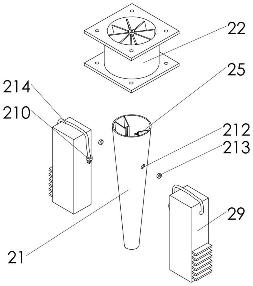
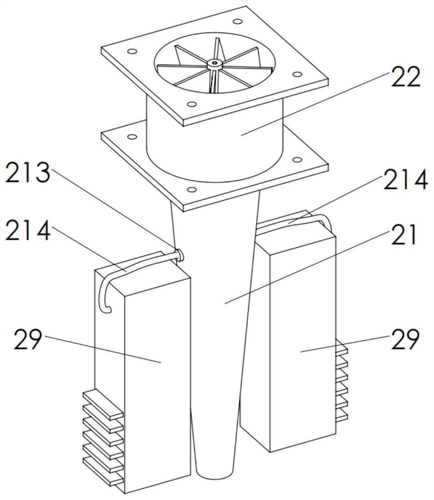
[0032] Embodiment one: see figure 1 and image 3 as shown,

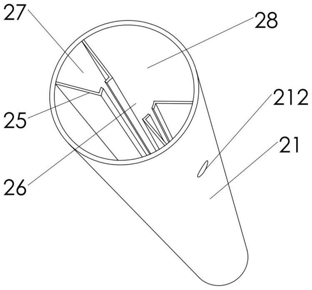
[0033]A deflector air channel assembly provided in this embodiment includes a channel 21 and a blowing device 22, the channel 21 includes an air inlet part 23 and an air outlet part 24, and the air inlet part 23 and the outlet part The wind part 24 forms a communication structure, the blowing device 22 is connected to the air inlet part 23, and the cross-sectional area of ​​the flow channel 21 perpendicular to the axis of the flow channel 21 is from the air inlet part 23 to the outlet. The air part 24 gradually decreases, and at least two deflectors 25 are arranged in the flow channel 21, one end of the deflector 25 is located at the air inlet part 23, and the other end is located at the air outlet part 24 , the plane where the deflector 25 is located and the inner wall of the flow channel 21 divide the flow channel 21 into several flow spaces 26 . The blowing device 22 blows air from the air inlet 23 into the air...

Embodiment 2

[0035] Embodiment two: see figure 1 as shown,

[0036] The difference between this embodiment and Embodiment 1 is that, as a preferred technical solution of this application, on a plane perpendicular to the axis of the flow channel 21, the end of the deflector 25 away from the inner wall of the flow channel 21 is placed The direction of the release tip 210 is bent. Further, on the ground plane perpendicular to the axis of the flow channel 21, bend the end of the flow guide plate 25 away from the inner wall of the flow channel 21 toward the direction of placing the release tip 210, and the bending position of the flow guide plate 25 is located at the opening of the flow space 26 The area of ​​the opening of the circulation space 26 is reduced, which plays a blocking role, preventing the negative ions in the circulation space 26 from escaping from the circulation space 26 into other circulation spaces 26 and being consumed by dust particles, further limiting the The movement r...


PUM


Abstract

The invention relates to an air flow channel assembly for a flow guide plate. The air flow channel assembly comprises a flow channel and an air blowing device, the flow channel comprises an air-inlet part and an air-outlet part, the air-inlet part and the air-outlet part form a communicating structure, an air blowing device is connected with the air-inlet part in a communicating mode, the cross section area, perpendicular to the axis of the flow channel, in the flow channel is gradually reduced from the air-inlet part to the air-outlet part, at least two flow guide plates are arranged in the flow channel, one end of each flow guide plate is located at the air-inlet part, the other end of each flow guide plate is located at the air-outlet part, and the flow channel is divided into a plurality of circulation spaces by the plane where the flow guide plates are located and the inner wall of the flow channel. According to the air flow channel assembly, the probability that negative ions move randomly in the flow channel, are combined with dust particles and are combined into large particles is reduced, the consumption of the negative ions in the flow channel is reduced, the content of the negative ions in air flowing out of the flow channel is increased, the flow guide plates are arranged, the effect of a reinforcing rib is achieved, and the stability of the flow channel structure is improved.

Description

technical field [0001] The invention relates to the field of air purification, in particular to an air channel assembly of a deflector. Background technique [0002] Air purifiers, also known as "air cleaners", air fresheners, and purifiers, refer to decoration pollution that can absorb, decompose or transform various air pollutants (generally including PM2.5, dust, pollen, odor, formaldehyde, etc.) , bacteria, allergens, etc.), products that effectively improve air cleanliness are mainly divided into household, commercial, industrial, and building. With the development of China's economy, environmental problems have become more and more serious in many cities, posing a great threat to people's health. Especially the problem of air quality. In recent years, with the development of heavy industry and house demolition, particulate pollutants (PM2.5, etc.) have spread in large quantities, and the air quality in various cities has generally decreased, causing various diseases a...

Claims


Application Information

Patent Timeline
Patent Type & Authority Applications(China)
IPC IPC(8): F24F8/80F24F13/26
CPCF24F13/26F24F3/16
Inventor 何育林杨颜蔚
Owner 何育林
Why Eureka
Try Eureka