
A compressed air foam generating device and its application method

A technology of compressed air foam and generating device, which is applied in separation methods, chemical instruments and methods, filtration and separation, etc. It can solve the problems that the quality and efficiency of fire extinguishing foam need to be further improved, and achieve the effect of convenient structure

Active Publication Date: 2022-05-10
西安同步电气有限责任公司
View PDF0 Cites 0 Cited by
  • Summary
  • Abstract
  • Description
  • Claims
  • Application Information

AI Technical Summary

Problems solved by technology

[0004] The purpose of the present invention is to provide a compressed air foam generating device, which solves the problem that the quality and efficiency of the preparation of the current fire extinguishing foam need to be further improved

Method used


Image

  • A compressed air foam generating device and its application method
  • A compressed air foam generating device and its application method
  • A compressed air foam generating device and its application method

Examples


Embodiment 1

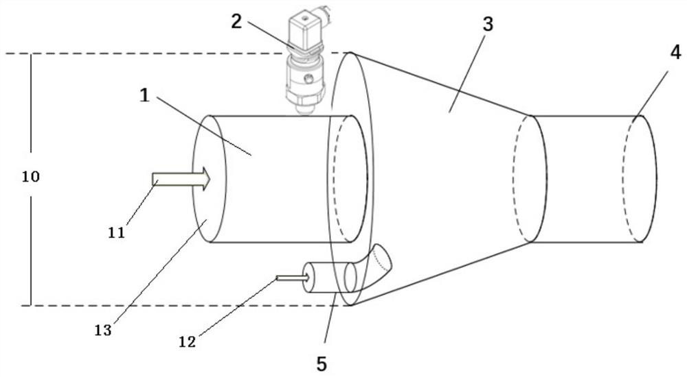
[0034] Such as figure 1 Shown is the basic graphic structure design of the foam mixing chamber 3. The foam mixture liquid inlet cylinder 1 is designed as a straight-through pipe of DN150. The raw material of the pipe can be changed according to different pressure and flow requirements. The entrance of the mixing chamber 3 is welded together by welding, and the outer wall contains a 1 / 2-inch hole for installing the pressure sensor 2. The foam mixing chamber 3 is a model of a conical shape with a large entrance and a small exit. The foam mixing The total length of the chamber 3 is 150mm, the taper of its circular table is 45°, the cross-section of the entrance is a circle with a diameter of 300mm, and an air inlet 5 with a diameter of 50mm is arranged on the underside, which is used for compressed air inlet, foam mixing chamber 3 The outlet cross section is a small circle with an inner diameter of 130mm and an outer diameter of 150mm. The spray cylinder 4 is connected to the ou...

Embodiment 2

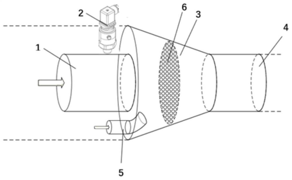
[0036] Such as figure 2 Shown is the design of adding a circular baffle plate with mesh 6 in the middle of the mixing chamber. The aperture of this circular mesh plate should be set to 1mm and its material should be related to the pressure and flow of mixing. The thickness of the board needs to be thick enough to withstand the required water pressure. The function of this mesh plate is to crush the large foam in the mixing chamber, so that the foam produced is more delicate and not easy to break, and has good fire extinguishing performance.

Embodiment 3

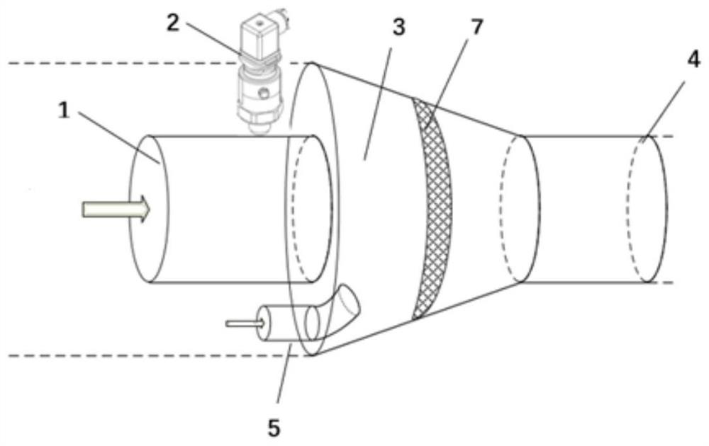
[0038] Such as image 3 As shown, a mesh arc-shaped baffle 7 is set in the middle of the foam mixing chamber. This setting is based on the structure of the foam mixing chamber 3. Because the inner wall of the foam mixing chamber 3 is slope-shaped, it should be fitted as much as possible when designing the baffle. The structure of the interface machinery, such equipment is generally more stable, not easy to damage and its tightness is better Figure II stronger. function with figure 2 same. Break the foam and improve the foam quality.


PUM


Abstract

The invention discloses a compressed air foam generating device and its application method. The device includes a foam mixed liquid delivery unit, an air delivery unit and a control unit, and also includes a mixing unit. The mixing unit includes a foam mixed liquid inlet cylinder, and the foam mixed liquid inlet The liquid cylinder is provided with a pressure sensor, the foam mixed liquid inlet cylinder is connected to a foam mixing chamber, the foam mixing chamber is connected to a spray cylinder, the spray cylinder is equipped with an electric butterfly valve, and an auxiliary mixing piece is arranged in the foam mixing chamber. The invention also discloses a method for using the device, which is carried out according to the following steps: step 1: start the generating device, the control unit controls the air delivery unit to deliver air and the foam mixture passing through the filter to achieve a dynamic balance, and form the foam air mixture; step 2: Install different auxiliary mixing parts according to different fires, and finally form the preset fire extinguishing foam. The structure and operation of the invention are relatively convenient, and the foam produced has better performance.

Description

technical field [0001] The invention belongs to the technical field of mechanical design, fire-fighting system and two-phase flow mixing, and in particular relates to a compressed air foam generating device, and also relates to a method for using the compressed air foam generating device. Background technique [0002] Compressed Air Foam System (Compressed Air Foam System, CAFS) is a new type of fire extinguishing system that has developed rapidly abroad in recent years. It has the advantages of high fire extinguishing efficiency, light weight, and less water consumption. Compressed Air Foam System (CAFS) generates The mechanism of foam is to pass a certain proportion of compressed air into the foam mixture, and generate foam after impact mixing. Compressed air is air compressed by external force. Air is compressible, and the air after the air compressor does mechanical work to reduce its volume and increase its pressure is called compressed air. Compressed air is an impor...

Claims


Application Information

Patent Timeline
Patent Type & Authority Patents(China)
IPC IPC(8): A62C5/02A62C31/12A62C37/00B01D29/01
CPCA62C5/02A62C31/12A62C37/00B01D29/01
Inventor 王建渊李英杰谭万奇何东克王海啸魏勤坡
Owner 西安同步电气有限责任公司
Learn More