Laboratory fume hood temperature and humidity intelligent regulation and control system
A technology of control system and fume hood, which is applied in the field of fume hood, can solve the problems of inconvenient adjustment of temperature and humidity of the fume hood, inconvenient use, and inability to adapt to the needs of the experimental environment, and achieve the effects of safe and reliable use, elevated temperature, and convenient installation and disassembly
- Summary
- Abstract
- Description
- Claims
- Application Information
AI Technical Summary
Problems solved by technology
Method used
Image
Examples
Embodiment 1
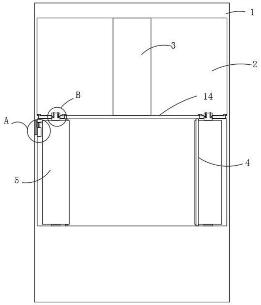
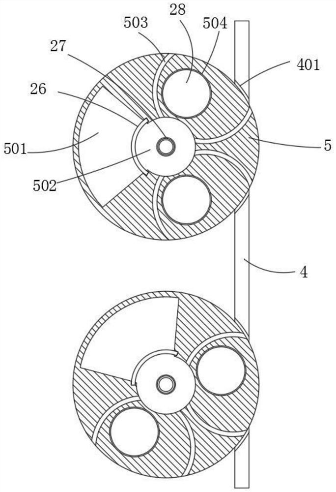
[0038] see Figure 1-7 , the laboratory fume hood temperature and humidity intelligent regulation and control system, including a cabinet body 1, a horizontal board 14 is arranged horizontally in the cabinet body 1, the top of the horizontal board 14 is the installation room 2, and the bottom of the horizontal board 14 is the operating room. Both sides are vertically fixed with a partition 4, and an installation gap is formed between the partition 4 and the adjacent inner wall of the operating room, and several gaps are provided on the partition 4.
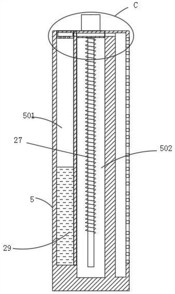
[0039] Several adjusting cylinders 5 are detachably installed in the installation gap, and the adjusting cylinders 5 correspond to the gaps one by one. A regulating module for regulating the interior environment of the operating room.
[0040] Both ends of the adjustment cylinder 5 are coaxially fixed with cylindrical connecting columns 11, wherein one connecting column 11 is rotatably connected with the inner bottom surface of t...
Embodiment 2
[0050] Please refer to Figure 8 , Figure 9 Further, the bottom of the second end cover 33 is open, and the inner side of the second end cover 33 is slidably connected to the connecting frame 42 along its depth direction, and the inner wall of the bottom of the second end cover 33 is movably sleeved with an inner cylinder 43, and the inner The bottom of the cylinder 43 has an inner cylinder bottom plate 39, an air hole 1 is eccentrically opened on the inner cylinder bottom plate 39, and a bottom cover 37 sleeved on the inner cylinder 43 is arranged below the inner cylinder bottom plate 39, and an air hole 2 is eccentrically opened on the bottom plate of the bottom cover 37. , and a drive motor is installed on the bottom plate 39 of the inner tube, the output shaft of the drive motor is connected with a rotating shaft 38 through a transmission member 41, the rotating shaft 38 moves through the bottom plate 39 of the inner tube, and is coaxially fixed with the bottom cover 37, ...
Embodiment 3
[0056] see Figure 4 as well as Figure 6 , in this embodiment, further, a circular dismounting hole 16 is opened on the horizontal plate 14, and the clamping plate 15 is rotatably connected to the disassembling hole 16, and a transfer hole is provided in the clamping plate 15 to cooperate with the connecting column 11 to penetrate A cavity 22 is provided at the bottom of the connecting column 11, and a socket 17 is also provided in the connecting column 11. The bottom end of the socket 17 communicates with the cavity 22, and the outer end of the cavity 22 is movably inserted with a positioning pin 23 for positioning. The inner end of the pin 23 is in contact with the rotating roller 21 which is rotatably connected to the inner chamber 22, and the driving member 18 is movably inserted in the socket 17, and the bottom end of the driving member 18 is connected to the driving disc 19 which is movably arranged at the bottom end of the socket 17. The driving disc 19 can drive the ...
PUM
 Abstract
Description
Claims
Application Information
 - R&D
- Intellectual Property
- Life Sciences
- Materials
- Tech Scout
- Unparalleled Data Quality
- Higher Quality Content
- 60% Fewer Hallucinations
Browse by: Latest US Patents, China's latest patents, Technical Efficacy Thesaurus, Application Domain, Technology Topic, Popular Technical Reports.
© 2025 PatSnap. All rights reserved.Legal|Privacy policy|Modern Slavery Act Transparency Statement|Sitemap|About US| Contact US: help@patsnap.com


