Grabbing mechanism for manipulator
A grasping mechanism and manipulator technology, applied in the field of manipulators, can solve problems such as falling objects, and achieve the effect of ensuring smooth gripping and facilitating automatic oil filling
- Summary
- Abstract
- Description
- Claims
- Application Information
AI Technical Summary
Problems solved by technology
Method used
Image

Examples
Embodiment 1
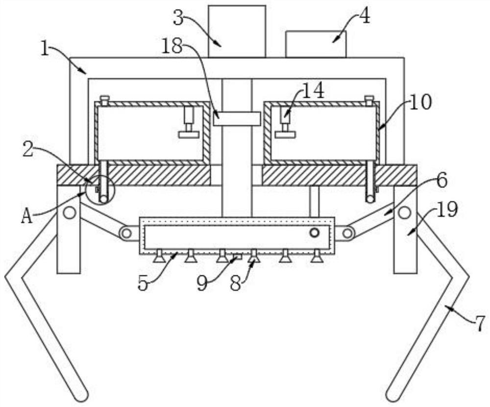
[0023] refer to Figure 1-3 , a gripping mechanism for a manipulator, comprising a mounting frame 1, the lower surface of the mounting frame 1 is fixedly connected with a support plate 2, and the upper surface of the mounting frame 1 is respectively provided with an electric telescopic rod 3 and a vacuum generator 4. The telescopic end of the telescopic rod 3 passes through the support plate 2 and is fixedly connected with the adsorption box 5, and the vacuum generator 4 communicates with the interior of the adsorption box 5 through a pipeline.
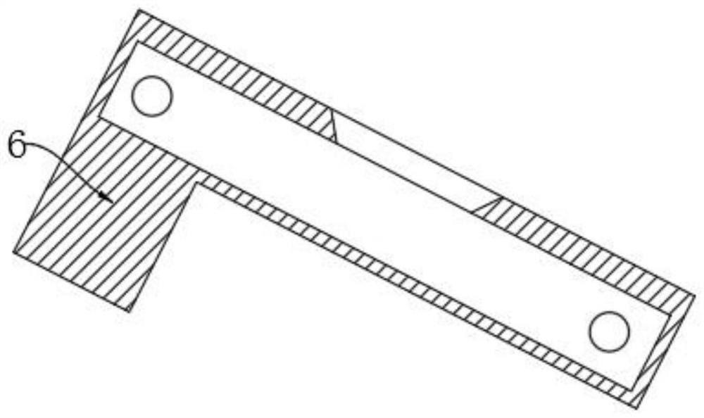
[0024] The surface of the adsorption box 5 is rotatably connected with a driving rod 6, the lower surface of the support plate 2 is fixedly connected with a concave block 19, and the inner wall of the concave block 19 is fixedly connected with a rotating shaft, and the surface of the driving rod 6 is provided with a rotating hole, and the rotating shaft The surface of the surface is rotatably connected with the inner wall of the rotat...
Embodiment 2
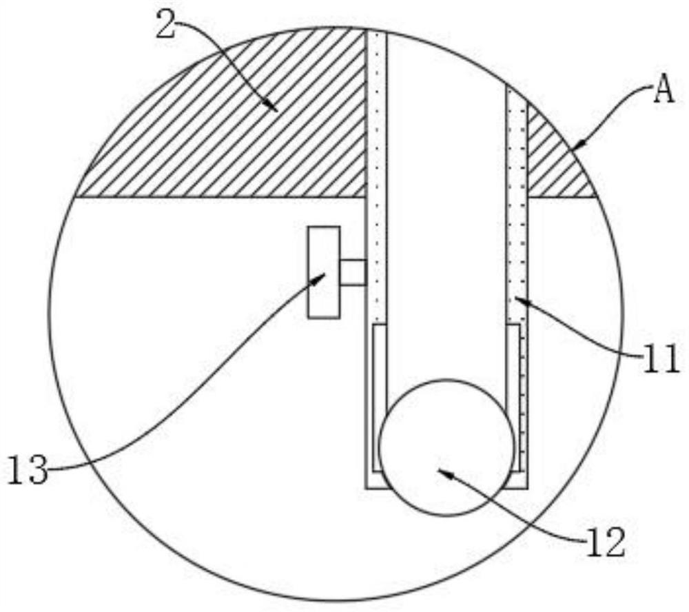
[0028] refer to figure 1 and Figure 4 , different from Embodiment 1, the inner top wall of the oil storage tank 10 is fixedly connected with a fixed cylinder 14, the inner wall of the fixed cylinder 14 is slidably connected with a T-shaped sliding rod 15, and the bottom end of the T-shaped sliding rod 15 is fixedly connected with a magnetic block 16. The inner top wall of the fixed cylinder 14 is fixedly connected with a spring 17, the bottom end of the spring 17 is fixedly connected with the top of the T-shaped slide bar 15, and the surface of the telescopic shaft of the electric telescopic rod 3 is fixedly connected with a magnetic ring 18.
[0029] In this embodiment, during the movement of the telescopic axis of the electric telescopic rod 3, the magnetic ring 18 moves accordingly, and the magnetic force adsorption between the magnetic ring 18 and the magnetic block 16 drives the magnetic block 16 to move downward, and the magnetic ring 18 moves beyond the magnetic block ...
PUM
 Abstract
Description
Claims
Application Information
 - R&D
- Intellectual Property
- Life Sciences
- Materials
- Tech Scout
- Unparalleled Data Quality
- Higher Quality Content
- 60% Fewer Hallucinations
Browse by: Latest US Patents, China's latest patents, Technical Efficacy Thesaurus, Application Domain, Technology Topic, Popular Technical Reports.
© 2025 PatSnap. All rights reserved.Legal|Privacy policy|Modern Slavery Act Transparency Statement|Sitemap|About US| Contact US: help@patsnap.com