
Composite material conical section shell forming mold and method

A technology of shell molding and composite materials, which is applied in the field of composite material molding, can solve problems such as inability to compact, achieve the effects of preventing potential safety hazards, ensuring the effect of compaction operations, and improving the effects of compaction operations

Active Publication Date: 2021-08-06
SHANGHAI COMPOSITES SCI & TECH CO LTD
View PDF10 Cites 1 Cited by
  • Summary
  • Abstract
  • Description
  • Claims
  • Application Information

AI Technical Summary

Problems solved by technology

The cover plate used for the pressure plate disclosed in this patent technology has the above-mentioned problem that it cannot be compacted, especially the deformation section of the flange

Method used


Image

  • Composite material conical section shell forming mold and method
  • Composite material conical section shell forming mold and method
  • Composite material conical section shell forming mold and method

Examples


Embodiment 1

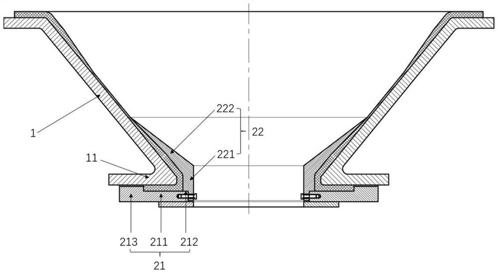
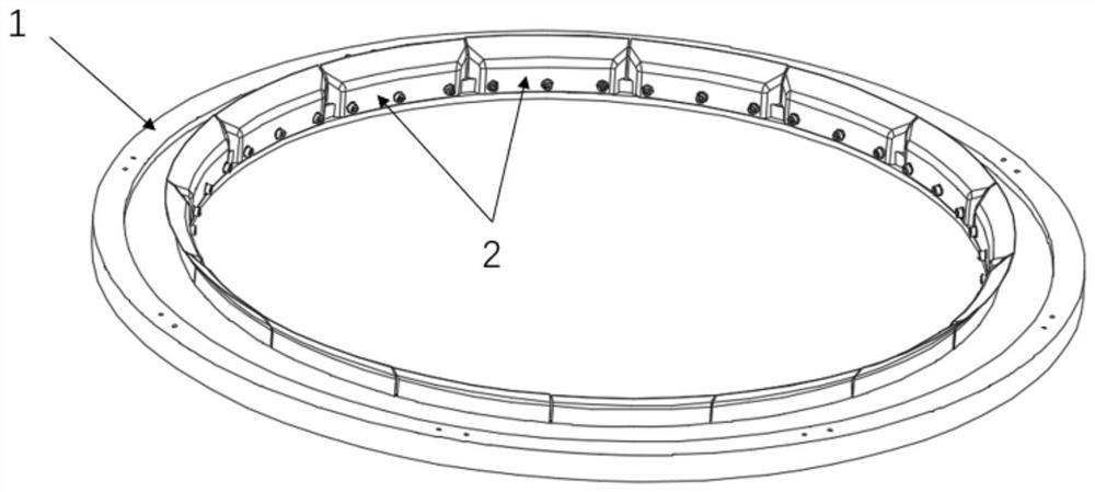
[0035] The present invention provides a mold for forming a composite material cone section shell, which includes a mold body 1 with a cone-shaped cylinder structure, and a pressing plate 2 for pressing prepreg laid on the mold body 1 . The openings at the upper and lower ends of the mold body 1 are used to connect with other structural sections. A flange connection section 11 is provided at the bottom of the mold body 1, and the flange connection section 11 is formed by folding outward along the edge of the mold body 1. The flange connection section 11 formed by turning outwards forms an angle α with the mold body 1, and the range of the angle α is less than 90 degrees. Generally, the angle α is half of the cone angle of the mold body 1. Complementary angles are formed, that is, the addition of the two equals 90°. When the angle α between the flange connection section 11 and the mold body 1 is less than 90°, the flange connection section 11 and the cylinder of the mold body 1 ...

Embodiment 2

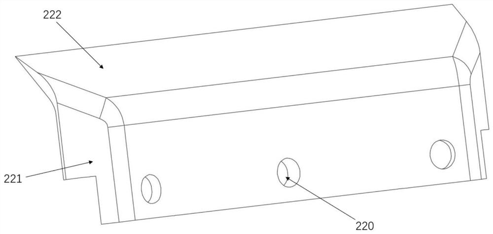
[0041] Embodiment 2 is formed on the basis of Embodiment 1. By optimizing the structure of the side pressure plate, the effect of the compaction operation is ensured, and the potential safety hazard caused by the accidental drop of the side pressure plate during installation is prevented. specifically:

[0042] The side pressure plate 22 in an L-shaped structure as a whole includes a straight section 221 and a tapered section 222, both of which are integrally formed. Wherein, the end of the straight section 221 away from the tapered section 222 is in contact with the surface of the support section 212, and the tapered section 222 is preferably an equilateral triangle or a right triangle structure, and from the tapered section 222 to the flat One end connected to the straight section 221 gradually becomes thinner toward the other end. The thickness design of the tapered section in the side pressure plate 22 can reduce the pressure of the upper layer laid at the corner of the m...

Embodiment 3

[0046] This embodiment 3 is formed on the basis of embodiment 1 or embodiment 2. By setting the surrounding bar section in the structure of the flange platen, it not only reduces the number of parts in the structure, but also makes the flange platen and the method on the mold body The distance between the flange connection sections can be adjusted to realize the quantitative adjustment of the compression amount of the flange connection section by the flange pressure plate. specifically:

[0047] One end of the flange platen 21 is provided with a surrounding strip section 213, and the function of the surrounding strip section 213 is to form an enclosure, that is, to block, the end of the prepreg laid on the surface of the flange connection section 11, so as to prevent the prepreg from flowing out . Thus, the surrounding strip section 213 is located at the end of the flange pressing plate 21 , and the surrounding strip section 213 , the flange surface pressing section 211 and t...


PUM


Abstract

The invention relates to the technical field of composite material forming, in particular to a composite material conical section shell forming mold and method. The composite material conical section shell forming mold comprises a mold body and a pressing plate; the mold body is a conical barrel, an opening in the bottom end of the mold body is turned over outwards to form a flange connecting section; the pressing plate comprises a flange pressing plate body and a side pressing plate body, the flange pressing plate body comprises a flange face pressing section and a supporting section, and the side pressing plate body is of an L-shaped structure; and after prepreg is laid on the surface of the mold body, the flange face pressing section covers the surface of the prepreg on the flange connecting section, the end part of the side pressing plate body is arranged on the supporting section, and the inner surface of the side pressing plate body is attached to the surface of the prepreg on the corner portion of the mold body. According to the composite material conical section shell forming mold and method, through the attached supporting design of the surface of the side pressing plate body and the surface of the flange pressing plate body, integral compaction operation can be carried out on the prepreg forming a flange structure, meanwhile, the side pressing plate body and the flange pressing plate body can move relatively due to the characteristic of the split structure, the prepreg can be fully compacted, and the problems of glue gathering, layering, pores and other defects after curing can be reduced.

Description

technical field [0001] The invention relates to the technical field of composite material forming, in particular to a composite material cone section shell forming mold and a method thereof. Background technique [0002] At present, a large number of high-strength composite materials are used in the load-bearing structure of aerospace launch vehicles. The main advantage of composite materials is that composite materials have a good weight reduction effect and can increase the payload of a single launch. As an important load-bearing structure of the final stage power cabin of the rocket body, the composite cone section is used to support payloads such as satellites. The typical structure of the composite material cone section is a thin-walled cone section, with thickened flanges at the front and rear ends, and a section of wall thickness gradient between the flange and the cone section. In order to improve the strength of the interface position on the flange, the wall thickn...

Claims


Application Information

Patent Timeline
IPC IPC(8): B29C70/34B29C70/54B29C33/30
CPCB29C70/342B29C70/54B29C33/308
Inventor 徐云研潘韵张志斌余娜史文锋沈辉李涛施静曹恒秀叶奇飞蔡克甲陈万新夏海祥张国凯
Owner SHANGHAI COMPOSITES SCI & TECH CO LTD
Learn More