Pneumatic transmission system, speed control method and transmission control method
A technology of pneumatic transmission and transmission speed, applied in conveyors, transportation and packaging, etc., can solve problems such as shocks in starting and stopping acceleration, setting different speeds, etc., to ensure accuracy and improve work efficiency.
- Summary
- Abstract
- Description
- Claims
- Application Information
AI Technical Summary
Problems solved by technology
Method used
Image
Examples
Embodiment 1
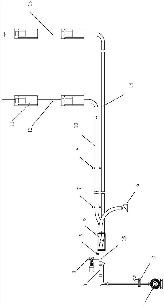
[0032] Such as figure 1 As shown, a pneumatic transmission system includes a fan 1, a vertical pipeline, a main horizontal pipeline 15 and a sub-horizontal pipeline, and the main horizontal pipeline 15 and the sub-horizontal pipeline are arranged along the horizontal direction and are located in the same building Workstations 11 on different floors in the center are connected sequentially through vertical pipelines, and the bottom of the vertical pipelines communicates with sub-horizontal pipelines.
[0033] The fan 1 is located on the main horizontal pipeline 15. Specifically, the fan 1 communicates with the main horizontal pipeline 15 through a three-way valve 2, and the three-way valve 2 can be switched to blowing mode, suction mode and no-load mode. In blowing mode, the fan 1 blows air into the system; in suction mode, the fan 1 sucks air into the system; in no-load mode, the fan 1 neither blows into the system nor blows into the system Inhale the wind.
[0034] Meanwhil...
Embodiment 2
[0039] Such as figure 1 As shown, the same parts of this embodiment and Embodiment 1 will not be repeated, the difference is: a speed control method for a pneumatic transmission system, comprising the following steps:
[0040] S100. In order to achieve a certain set transmission speed, the control terminal sends a control signal to the electric actuator of the regulating valve 4 according to the pre-calibrated value, adjusts the opening of the regulating valve 4, and collects the arrival signals of the transmission bottles through the speed photoelectric sensor 8 and the departure signal, and calculate the real-time transmission speed according to the time difference between the arrival signal and the departure signal.
[0041] S200. The control terminal compares the real-time transmission speed with the set transmission speed to correct the opening of the regulating valve 4. Specifically, when the real-time transmission speed is lower than the set transmission speed, increase...
Embodiment 3
[0045] Such as figure 1 As shown, the same parts of this embodiment as those of Embodiment 1 and Embodiment 2 will not be repeated, but the difference is:
[0046] When the transfer bottle is transferred between different workstations 11 in the same vertical pipeline, adjust the opening of the regulating valve 4, and when the pressure in the system reaches the set pressure corresponding to the set transmission speed, the opening of the regulating valve 4 remains unchanged , the transfer bottle is directly transferred to the target workstation in the vertical pipeline at the set transfer speed.
[0047] When the transport bottle is transported from top to bottom in the same vertical pipeline, the fan 1 is not working, and the transport bottle falls from the originating station in the vertical pipeline by its own gravity. Since the fan 1 does not start and the pipeline is sealed, the pipeline The air in the bottle can only flow out from the gap between the transfer bottle and t...
PUM
 Abstract
Description
Claims
Application Information
 - R&D
- Intellectual Property
- Life Sciences
- Materials
- Tech Scout
- Unparalleled Data Quality
- Higher Quality Content
- 60% Fewer Hallucinations
Browse by: Latest US Patents, China's latest patents, Technical Efficacy Thesaurus, Application Domain, Technology Topic, Popular Technical Reports.
© 2025 PatSnap. All rights reserved.Legal|Privacy policy|Modern Slavery Act Transparency Statement|Sitemap|About US| Contact US: help@patsnap.com

