
Engine cylinder cover structure

A technology of engine cylinder head and cylinder head, which is applied in the direction of engine components, machines/engines, cylinder heads, etc., can solve the problems of pressure loss, increase in the number of parts, and increase in the number of parts, so as to solve pressure loss, reduce costs, and reduce parts Quantity effect

Pending Publication Date: 2022-07-29
KUBOTA LTD
View PDF2 Cites 0 Cited by
  • Summary
  • Abstract
  • Description
  • Claims
  • Application Information

AI Technical Summary

Problems solved by technology

[0003] It can be seen that there are problems shown in the following A to C in the above-mentioned prior art: A. A high-pressure resistant fuel pipe is provided, so the fuel pipe will cause a pressure loss; B. Each fuel injection device requires a fuel pipe, so, The number of parts increases; C. Both the fuel pressure accumulator and the fuel injection device require support members, and the number of parts increases

Method used


Image

  • Engine cylinder cover structure
  • Engine cylinder cover structure
  • Engine cylinder cover structure

Examples


Embodiment Construction

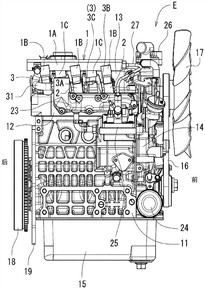
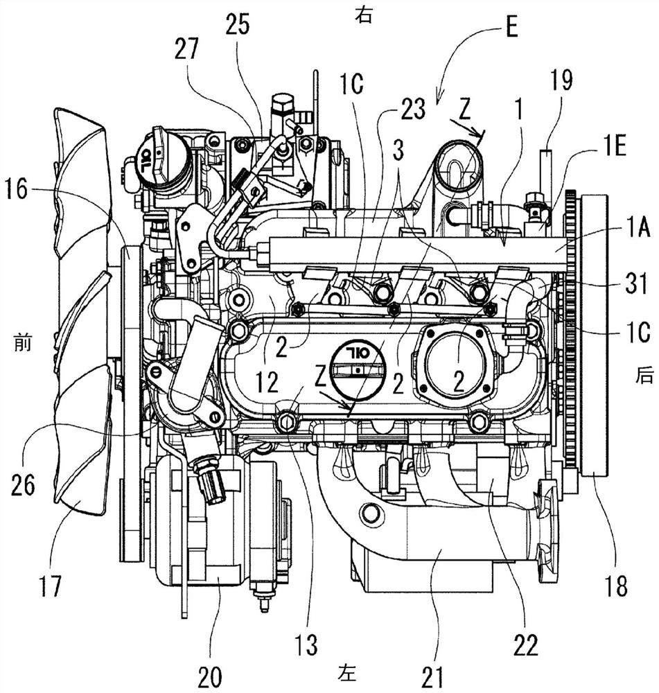
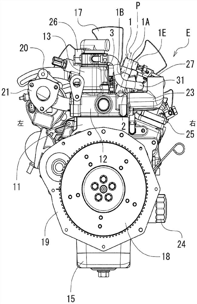
[0032] Hereinafter, in the case of an industrial diesel engine (hereinafter abbreviated as "engine") mounted on an agricultural tractor or construction equipment, an embodiment of the engine head structure of the present invention will be described with reference to the drawings. In addition, the side where the cooling fan is located in the engine is defined as the front, the side where the flywheel is located is defined as the rear, the side where the exhaust manifold is located (exhaust side) is defined as the left, and the side where the intake manifold is located (the intake side) is defined as the left. gas side) is defined as right.

[0033] Figure 1 to Figure 3 An inline three cylinder common rail industrial diesel engine is shown. In this engine E, the cylinder head 12 is attached to the cylinder block 11 , and the cylinder head cover 13 is attached to the cylinder head 12 . The transmission case 14 and the oil pan 15 are assembled in front of and below the cylinder...


PUM


Abstract

The present invention provides an engine cylinder head structure which can solve the following problems as much as possible by further designing a fuel accumulator, a support structure thereof and the like: omitting or shortening a high-pressure-resistant fuel pipe as much as possible, simplifying or omitting a support frame of the fuel accumulator or / and a fuel injection device, and reducing the number of components. An engine cylinder head structure in which a support frame (3) for attaching a fuel accumulator (1) having a joining section (1B) joined to a fuel injection device (2) to a cylinder head (12) is disposed beside the fuel injection device (2) or between adjacent fuel injection devices (2), the support frame (3) having: a mounting section (3C) on which the fuel accumulator (1) is mounted; a mounting leg part (3A) which extends from the mounting part (3C) and which is mounted to the cylinder head (12); and an alignment leg part (3B) extending from the loading part (3C) and used for positioning relative to the cylinder head (12).

Description

technical field [0001] The present invention relates to a structure around a cylinder head of an engine having a fuel accumulator, such as an industrial diesel engine or a motor vehicle engine, that is, an engine cylinder head structure. Background technique [0002] Generally, in an engine using a fuel accumulator (common rail system, etc.), high-pressure fuel is accumulated in the fuel accumulator by a fuel pressure feed pump, and a high-pressure fuel is installed from the fuel accumulator to a fuel injection device (injector) arranged in a cylinder. fuel piping. As such a technique, the invention disclosed in Patent Document 1 or Patent Document 2 is known. [0003] It can be seen that the above-mentioned prior art has the following problems as shown in A to C: A. High pressure-resistant fuel piping is provided, so pressure loss occurs in the fuel piping; B. Each fuel injection device requires fuel piping, so, The number of parts increases; C. Both the fuel accumulator ...

Claims


Application Information

Patent Timeline
Patent Type & Authority Applications(China)
IPC IPC(8): F02M55/02F02F1/24
CPCF02F1/24F02M55/025F02M2200/85F02M61/14F02M2200/855F02M2200/857F02M2200/852F02F1/242
Inventor 田村亮藤田健介尾曾洋树小林泰松延新吾奥田贡
Owner KUBOTA LTD
Learn More