
Movable emergency bridge device for roads and bridges

A technology for bridges and emergency bridges, applied in bridges, bridge parts, bridge forms, etc., can solve the problems of easy shaking of the bridge deck, dangerous installation operations, and inability to achieve emergency effects, so as to increase the use distance and reduce space. The use and transportation effect of

Inactive Publication Date: 2021-08-06
曹瑞强
View PDF4 Cites 2 Cited by
  • Summary
  • Abstract
  • Description
  • Claims
  • Application Information

AI Technical Summary

Problems solved by technology

Although the device has many beneficial effects, there are still the following problems: the structure of the device is too simple, only slant plates are set on both sides to build a temporary bridge, not only the distance is too short, but also can be completed directly with other plates, which cannot meet the emergency effect, and the slant plate is set for rotation and connection, the angle cannot be fixed, and there is a potential safety hazard if it is used rashly. In addition, although other existing patented technologies such as CN201410410704 / CN204644855U / CN207700031U all adopt a retractable hinge structure to reach the river ditch or the opposite side of the partition, However, in this type of design scheme, there are the following defects: because the bridge deck of the hinged structure continues to elongate before reaching the other bank, it causes its downward deformation. The actual required length requires subsequent adjustments and vertical adjustments with the help of other mechanisms. In addition, in the above solutions, handrails and fences need to be installed separately before the telescopic laying is completed. The bridge deck is prone to shaking, so the installation operation will be more dangerous. In view of this, we propose a movable emergency bridge device for road bridges

Method used


Image

  • Movable emergency bridge device for roads and bridges
  • Movable emergency bridge device for roads and bridges
  • Movable emergency bridge device for roads and bridges

Examples


Embodiment Construction

[0024] In describing the present invention, it should be understood that the terms "center", "longitudinal", "transverse", "length", "width", "thickness", "upper", "lower", "front", " Orientation indicated by rear, left, right, vertical, horizontal, top, bottom, inside, outside, clockwise, counterclockwise, etc. The positional relationship is based on the orientation or positional relationship shown in the drawings, and is only for the convenience of describing the present invention and simplifying the description, rather than indicating or implying that the referred device or element must have a specific orientation, be constructed and operated in a specific orientation, Therefore, it should not be construed as limiting the invention.

[0025] In the description of the present invention, "plurality" means two or more, unless otherwise specifically defined.

[0026] In the description of the present invention, it should be noted that, unless otherwise specified and limited, t...


PUM


Abstract

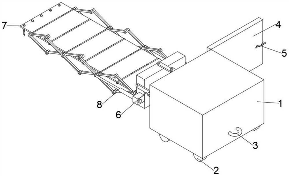
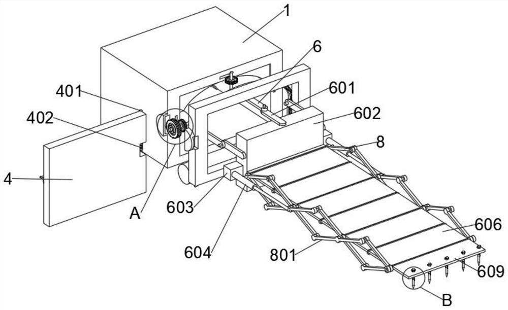
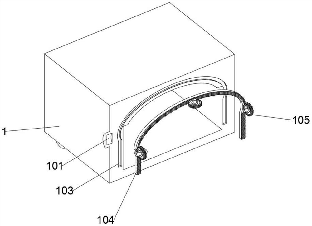
The invention discloses a movable emergency bridge device for roads and bridges, and belongs to the technical field of roads and bridges. The movable emergency bridge device for roads and bridges comprises a movable box, wherein a plurality of connecting plates are linearly arranged on the front side of a movable block at equal intervals, two limiting cylinders B are symmetrically welded to the middle of one part of the connecting plates, two limiting cylinders C are symmetrically arranged on the front side and the rear side of the outer side of the other part of the connecting plates, limiting plates are arranged on the front sides of the connecting plates, two limiting cylinders D are symmetrically welded to the rear sides of the limiting plates, connecting rods A are symmetrically and rotationally connected to the outer sides of the connecting plates through pin shafts, connecting rods B are rotationally connected to the front sides of the connecting rods A through pin shafts, and the structures are tightly matched, so that the temporary bridge can be automatically unfolded and folded by arranging the connecting rods and the connecting plates, the device can be folded when not in use to reduce space and facilitate transportation, meanwhile, the device can be unfolded when in use to increase the effective use distance, and the device device can meet the requirements of different conditions.

Description

technical field [0001] The invention relates to the technical field of road bridges, in particular to a movable emergency bridge device for road bridges. Background technique [0002] Bridges generally refer to structures erected on rivers, lakes and seas to allow vehicles and pedestrians to pass smoothly. In order to adapt to the modern high-speed development of the transportation industry, bridges are also extended to buildings that cross mountain streams, poor geology or meet other transportation needs to make traffic more convenient. Most bridges are completely fixed to the foundation, that is, immovable, but in some specific situations, such as flood disasters or other rescues that need to cross terrain or during bridge construction, a temporary bridge that can be erected quickly is required. However, the current bridge structure does not support movement or the construction progress is slow. The prior art publication number is CN112030715A, which provides a movable e...

Claims


Application Information

Patent Timeline
Patent Type & Authority Applications(China)
IPC IPC(8): E01D15/10E01D15/12E01D19/00
CPCE01D15/10E01D15/12E01D15/124E01D19/00
Inventor 张勋
Owner 曹瑞强
Learn More