A speed-limited non-dead-end painting wall painting device for construction machinery
A kind of construction machinery and no dead angle technology, applied in the direction of construction, building structure, etc., can solve the problems of inability to paint the walls comprehensively, the effect of painting is not good, and the efficiency of painting is low, so as to improve the quality of painting and reduce labor costs , the effect of convenient operation
- Summary
- Abstract
- Description
- Claims
- Application Information
AI Technical Summary
Problems solved by technology
Method used
Image
Examples
Embodiment 1
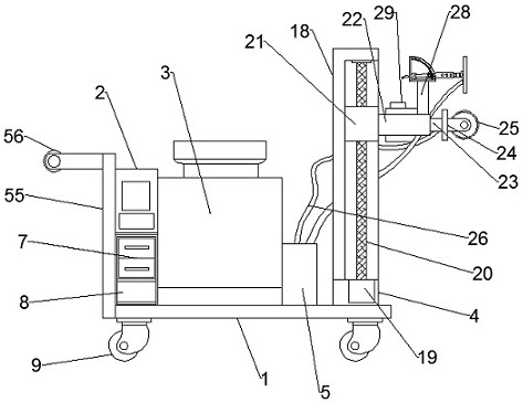
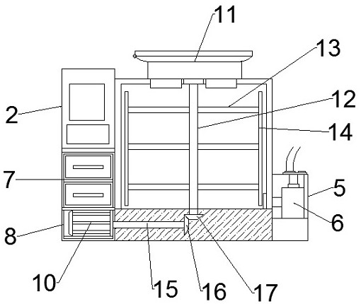
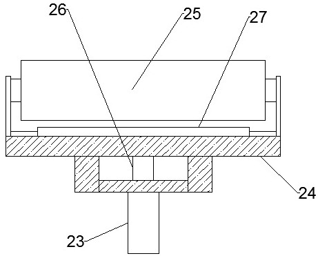
[0032] like Figure 1-9 As shown in the figure, the speed-limited non-dead-end painting wall painting device for construction machinery according to the embodiment of the present invention includes a support plate 1, and a control box 2 is provided on one side of the upper end of the support plate 1, and the support plate 1 is close to the A stirring box 3 is arranged in the middle of the upper end of one side of the control box 2 , a painting device 4 is arranged on the side of the support box away from the stirring box 3 , and the middle of the upper end of the support plate 1 close to the stirring box 3 is arranged There is a connection box 5, the inside of the connection box 5 is provided with a water pump 6 connected to the stirring box 3, the upper end of the control box 2 is provided with a control panel, and the control box 2 is located at the bottom end of the control panel A battery box 7 is provided, and a connection frame 8 is provided at the bottom end of the cont...
Embodiment 2
[0036] like Figure 1-9 As shown, the four corners of the lower end of the supporting plate 1 are provided with receiving plates, the bottom ends of the receiving plates are all provided with universal wheels 9, and the receiving plates are fixed with the supporting plate 1 by several bolts connect. A motor 10 is arranged inside the connection frame 8, a feeding frame 11 is arranged on the upper end of the stirring box 3, and a feeding hopper inserted into the stirring box 3 is arranged on both sides of the lower end of the feeding frame 11. A stirring rod 12 is arranged in the inner middle of the stirring box 3 , a plurality of stirring blades 13 are arranged on the stirring rod 12 , and a transverse blade 14 is arranged at one end of the stirring blade 13 . The bottom end of the stirring box 3 supports There is a linkage rod 15 connected to the motor one 10 inside, one end of the linkage rod 15 is provided with a bevel gear one 16, and the bottom end of the stirring rod is ...
PUM
 Abstract
Description
Claims
Application Information
 - R&D
- Intellectual Property
- Life Sciences
- Materials
- Tech Scout
- Unparalleled Data Quality
- Higher Quality Content
- 60% Fewer Hallucinations
Browse by: Latest US Patents, China's latest patents, Technical Efficacy Thesaurus, Application Domain, Technology Topic, Popular Technical Reports.
© 2025 PatSnap. All rights reserved.Legal|Privacy policy|Modern Slavery Act Transparency Statement|Sitemap|About US| Contact US: help@patsnap.com


