Multi-point array response control directional diagram synthesis with maximum gain

A technology of pattern synthesis and maximum gain, applied in the field of antennas, it can solve the problems of large amount of computation, long time, and inability to control the main lobe area, and achieves the effect of small amount of computation, speeding up the overall efficiency, and reducing the amount of computation.

Pending Publication Date: 2021-08-06
XIDIAN UNIV
View PDF0 Cites 0 Cited by
  • Summary
  • Abstract
  • Description
  • Claims
  • Application Information

AI Technical Summary

Problems solved by technology

[0004] However, the use of optimization algorithms such as particle swarm optimization and genetic algorithms requires a global search of the antenna array, and the amount of calculation is too large. Especially in the application scenario of large-scale antenna arrays, the global search will take too long; The optimization theory cannot realize the precise adjustment operation of the antenna array pattern; only the adaptive array theory is used to minimize the difference between the expected and the characteristics of the antenna array pattern by imposing virtual interference on the antenna array pattern, and it is impossible to control the main lobe area, and the power value of the virtual interference is selected according to experience, which cannot accurately achieve the desired antenna array pattern characteristics

Method used


Image

  • Multi-point array response control directional diagram synthesis with maximum gain
  • Multi-point array response control directional diagram synthesis with maximum gain
  • Multi-point array response control directional diagram synthesis with maximum gain

Examples


Embodiment

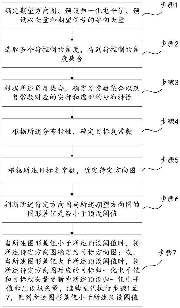
[0021] See figure 1 , a schematic flowchart of a maximum gain multi-point array response control pattern synthesis method provided by an embodiment of the present invention. The methods include:

[0022] Step 1: Determine the expected pattern and preset normalized level value L k-1 (θ,θ 0 ), preset weight vector w k-1 and the steering vector a(θ 0 ), where k represents the number of iterations, L k-1 (θ,θ 0 ) represents the normalized level at θ in the pattern obtained in the k-1th iteration, θ 0 Indicates the direction of arrival of the desired signal.

[0023] The invention controls pattern synthesis through multi-point array response control, so that the performance of the pattern of the large-scale array antenna approaches the performance of the expected pattern. In the present invention, when the pattern obtained by the k-1 iteration does not meet the preset threshold, the preset normalized level value L corresponding to the pattern obtained by the k-1 iteration ...


PUM


Abstract

The invention discloses a multi-point array response control directional diagram synthesis method with the maximum gain. The method comprises the steps of determining an expected directional diagram, a preset normalized level value, a preset weight vector and a steering vector of an expected signal; selecting a plurality of to-be-controlled angles to obtain a to-be-controlled angle set; according to the angle set, determining a complex constant set and distribution characteristics of a real part and an imaginary part corresponding to complex constants; determining a target complex constant according to the distribution characteristics; determining a to-be-determined directional diagram according to the target complex constant; judging whether a graph difference value between the to-be-determined directional diagram and the expected directional diagram is smaller than a preset threshold value or not; when the graph difference value is smaller than the preset threshold value, determining the to-be-determined directional diagram as a target directional diagram; or, when the graph difference value is greater than the preset threshold value, continuing to iteratively execute the steps 1 to 7 until the graph difference value is smaller than the preset threshold value. The method can flexibly control the directional diagram, and reduces the calculation amount in the comprehensive process of the directional diagram.

Description

technical field [0001] The invention belongs to the technical field of antennas, and in particular relates to a multi-point array response control pattern synthesis with maximum gain. Background technique [0002] With the development of antenna technology field, antenna array pattern synthesis technology is widely used in radar and communication. The antenna array pattern refers to the image of the antenna radiation electromagnetic field on a spherical surface with the antenna as the center and a certain distance as the radius along with the spatial angle distribution. The antenna array pattern is an important basis for measuring the performance of the antenna array. Through the antenna array direction The graph synthesis technology weights each antenna in the antenna array, and can obtain the required characteristics of the antenna array pattern. [0003] In the prior art, antenna array pattern synthesis techniques such as optimization algorithm, convex optimization theor...

Claims


Application Information

Patent Timeline
Patent Type & Authority Applications(China)
IPC IPC(8): G01S7/02
CPCG01S7/02
Inventor 兰岚吕微慧廖桂生朱圣棋许京伟张玉洪邓敬亚
Owner XIDIAN UNIV
Why Eureka
Try Eureka