Supercharge Your Innovation With Domain-Expert AI Agents!

Light guide module

A technology of light guide module and light guide column, which is applied in the direction of light guide, optics, optical components, etc.

Active Publication Date: 2021-08-06
DELTA ELECTRONICS INC
View PDF7 Cites 0 Cited by
  • Summary
  • Abstract
  • Description
  • Claims
  • Application Information

AI Technical Summary

Problems solved by technology

[0005]The main purpose of this case is to provide a light guide module to solve and improve the problems and shortcomings of the aforementioned prior art

Method used


Image

  • Light guide module
  • Light guide module
  • Light guide module

Examples


Embodiment Construction

[0054] Some typical embodiments embodying the features and advantages of the present application will be described in detail in the description in the following paragraphs. It should be understood that the present application can have various changes in different aspects without departing from the scope of the present application, and that the description and drawings therein are used for illustration in nature rather than for limiting the present application.

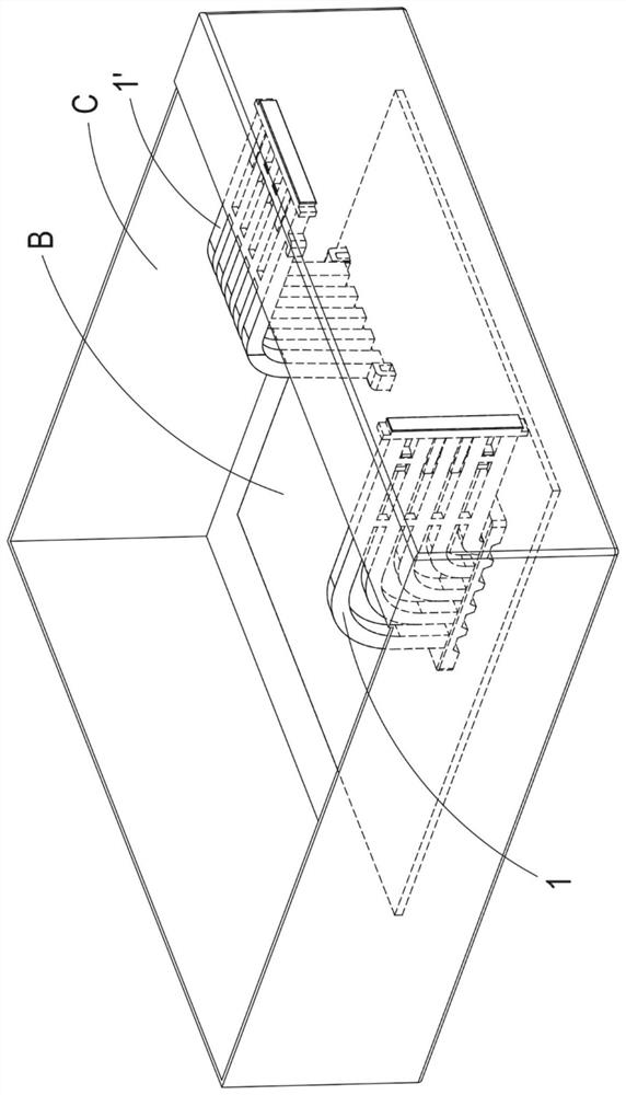
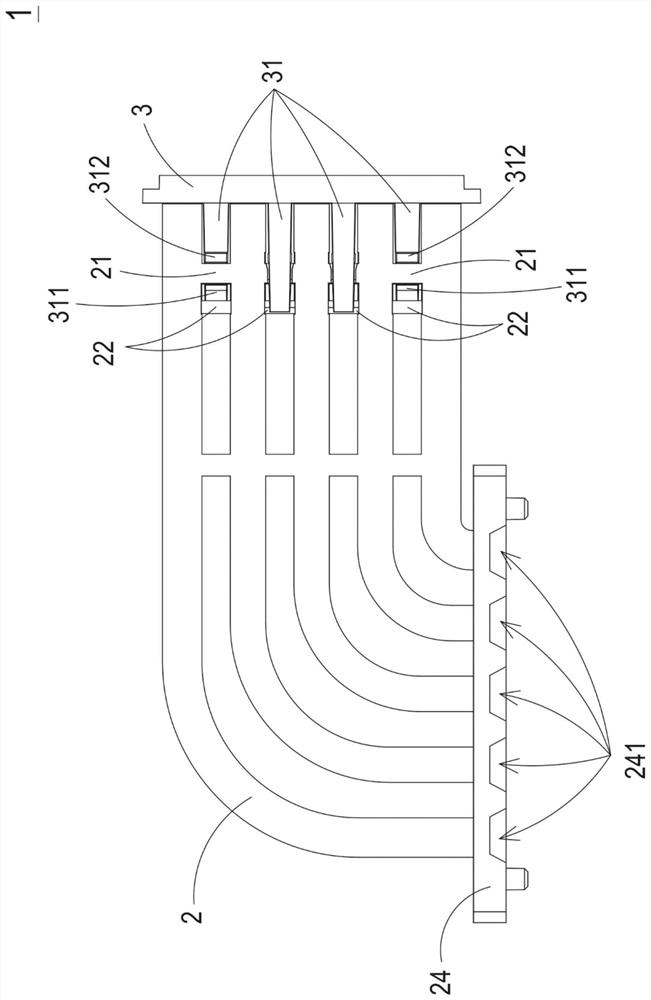
[0055] see Figure 1A , Figure 1B , figure 2 , image 3 and Figure 4A . Figure 1A It is a structural schematic diagram disclosing the first embodiment and the second embodiment of the light guide module applied to electronic equipment. Figure 1B It is a structural schematic diagram of the light guide module disclosing the first embodiment of the present application. figure 2 It is an exploded view of the structure of the light guide module disclosed in the first embodiment of the present application. image ...


PUM


Abstract

A light guide module comprises a light guide assembly and a decorative plate. The light guide assembly comprises a base, a plurality of light guide columns and a plurality of first connecting parts. Each light guide column is provided with a light inlet part and a light outlet part, and the light inlet part is connected with the base. The first connecting parts are connected between the light guide columns. The decorative plate comprises a first surface and a plurality of extension parts. The first surface is abutted against the light emitting portions of the plurality of light guide columns. The extension parts extend from the first surface, and each extension part comprises a first convex part and a second convex part. Each second convex part is arranged between the corresponding first convex part and the first surface. The first convex parts and the second convex parts of part of the extension parts extend along the first direction, and the first convex parts and the second convex parts of the rest of the extension parts extend along the second direction. The first connecting part of the light guide assembly is clamped between the first convex parts and the second convex parts of the extension parts.

Description

technical field [0001] This case relates to a light guide module, especially a light guide module in which a light guide component and a decorative plate have corresponding fixing structures. Background technique [0002] In order to achieve multi-function and high performance, today's electronic devices continue to develop towards a high level of integration. At the same time, with the miniaturization of electronic equipment, the configuration density of components in the electronic equipment is gradually increased, and the size of the components is also increasingly reduced. Under such circumstances, how to maintain the accuracy of component assembly so that the functions of electronic devices can be performed normally has always been one of the key points in this field. [0003] Generally, electronic devices usually have a graphic display effect, so that users can understand the current state of the electronic device. Most of the known pattern display methods use a plur...

Claims


Application Information

Patent Timeline
Patent Type & Authority Applications(China)
IPC IPC(8): G02B6/00
CPCG02B6/0086G02B6/0001G02B6/0081G02B6/0078G02B6/24H05K5/02
Inventor 谢世祺
Owner DELTA ELECTRONICS INC
Features
  • R&D
  • Intellectual Property
  • Life Sciences
  • Materials
  • Tech Scout
  • Unparalleled Data Quality
  • Higher Quality Content
  • 60% Fewer Hallucinations
Learn More