A Vibration Signal Separation Method of Tubular Turbine

A technology of tubular turbines and vibration signals, which is applied in the recognition of patterns in signals, computer parts, characters and patterns, etc., to achieve the effect of improving the discrimination.

Active Publication Date: 2022-04-19
XIAN UNIV OF TECH
View PDF0 Cites 0 Cited by
  • Summary
  • Abstract
  • Description
  • Claims
  • Application Information

AI Technical Summary

Problems solved by technology

Therefore, the judgment of cavitation is particularly important. However, when cavitation occurs, it is often accompanied by other excitation sources (hydraulic, mechanical and electrical, etc.). How to quickly and accurately separate the cavitation signal from the monitored signal source , especially the accurate identification of cavitation inception is still the difficulty of cavitation testing

Method used


Image

  • A Vibration Signal Separation Method of Tubular Turbine
  • A Vibration Signal Separation Method of Tubular Turbine
  • A Vibration Signal Separation Method of Tubular Turbine

Examples


Embodiment Construction

[0054] The present invention will be described in detail below in conjunction with the accompanying drawings and specific embodiments.

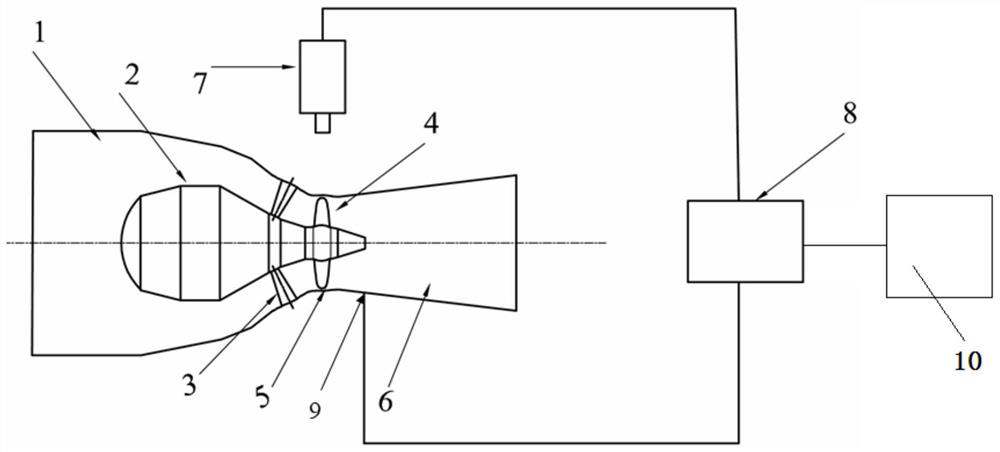
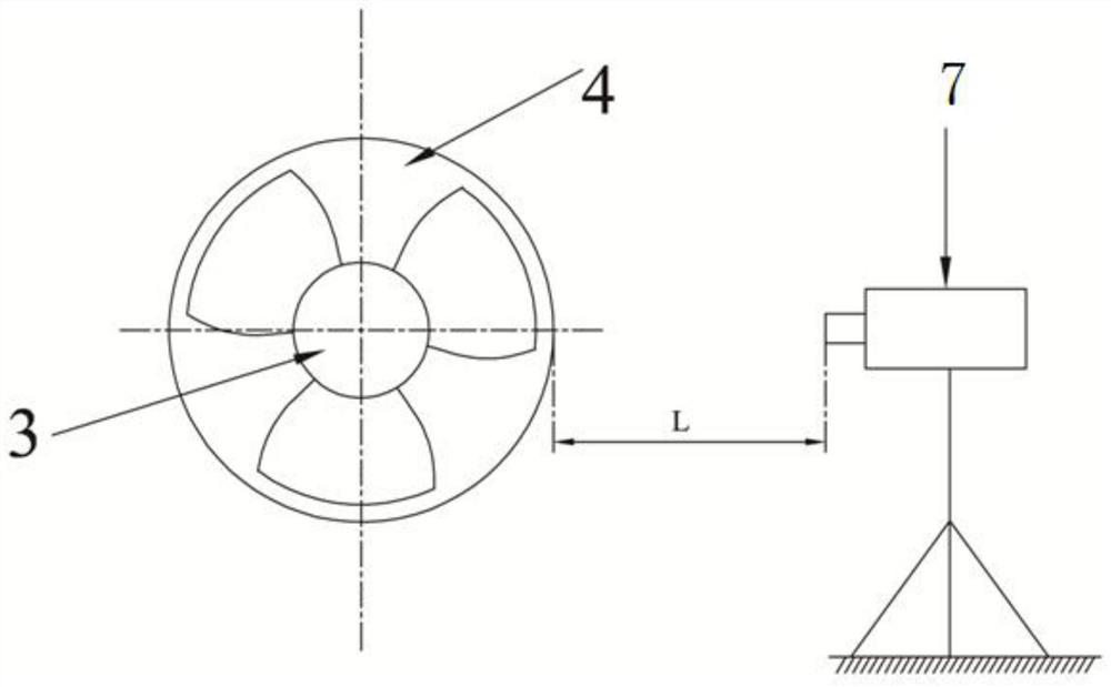
[0055]A method for separating vibration signals of a tubular water turbine according to the present invention adopts a water turbine vibration data acquisition test system, which includes a water inlet pipe 1, a runner chamber 5, and a draft pipe 6 connected in sequence, and the water inlet pipe 1 is sequentially arranged according to the water flow direction. Bulb body 2, guide vane 3, guide vane 3 is connected with runner 4, and runner 4 is positioned at runner chamber 5, and the outside of runner chamber 5 is provided with laser vibrometer 7, and the measuring point of laser vibrometer 7 and The horizontal distance at the position corresponding to the runner chamber 5 is L, and the laser vibrometer 7 is electrically connected to the data acquisition system 8 through wires, and the data acquisition system 8 is connected to the console 9. Spe...


PUM


Abstract

The technical solution adopted in the present invention is a method for separating the vibration signal of a tubular water turbine, specifically: adopting a laser vibrometer to collect the vibration velocity signal of the runner, and obtaining the time series x(t ), and then filtered by a low-pass filter to obtain the filtered vibration velocity signal x 1 (t), and then perform mean value processing to obtain the processed vibration velocity signal x' 1 (t), and then perform whitening processing, variational mode decomposition, and dimensionality reduction processing to obtain a new signal u’(t), and then perform independent component analysis on u’(t) to separate the signal u. The invention can quickly and accurately separate vibration signals caused by cavitation from general vibration signals.

Description

technical field [0001] The invention belongs to the technical field of water turbines and relates to a vibration signal separation method of a tubular water turbine. Background technique [0002] Cavitation phenomenon commonly exists in hydraulic machinery, which is one of the important reasons for the decrease of hydraulic machinery efficiency and output, unit vibration and unstable operation. Cavitation may also lead to cavitation erosion, and cavitation collapse can cause damage to the surface of unit components. Cavitation erosion is more severely damaged under the combined action of sediment wear, which seriously affects the reliable operation and service life of the unit. Usually, cavitation can be divided into airfoil (airfoil) cavitation, cavity cavitation, gap cavitation, and other cavitation caused by local deflow according to the location where cavitation occurs. Among the above cavitations, gap cavitation may cause mechanical damage and have a certain impact on...

Claims


Application Information

Patent Timeline
Patent Type & Authority Patents(China)
IPC IPC(8): G06K9/62G06K9/00G01H9/00
CPCG01H9/00G06F2218/04G06F2218/08G06F18/2135G01M7/00G01M15/14F03B17/061F05B2240/14F05B2240/12F05B2260/83
Inventor 冯建军李康罗兴锜朱国俊吴广宽
Owner XIAN UNIV OF TECH
Why Eureka
Try Eureka