Pharmaceutical mixing machine with automatic feeding mechanism

An automatic feeding and mixer technology, applied in mixers, shaking/vibrating/vibrating mixers, mixer accessories, etc., can solve the problems that the mixing effect cannot meet the production needs, and the large particle powder cannot be effectively pulverized.

Active Publication Date: 2021-08-10
重庆天致药业股份有限公司
View PDF8 Cites 0 Cited by
  • Summary
  • Abstract
  • Description
  • Claims
  • Application Information

AI Technical Summary

Problems solved by technology

[0003] The existing pharmaceutical mixer cannot effectively pulverize the large particle powder doped in the powder when stirring and mixing the powder, and the stirring effect cannot meet the production needs

Method used


Image

  • Pharmaceutical mixing machine with automatic feeding mechanism
  • Pharmaceutical mixing machine with automatic feeding mechanism
  • Pharmaceutical mixing machine with automatic feeding mechanism

Examples


Embodiment 1

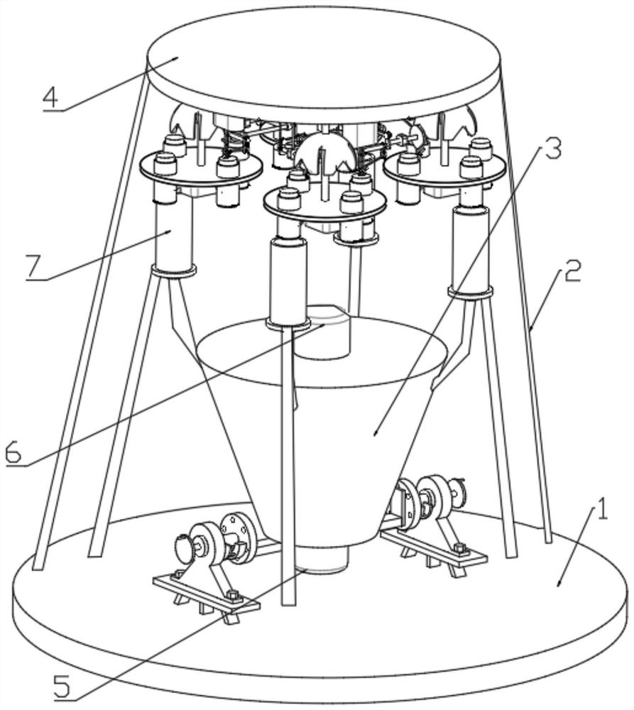
[0030] see Figure 1-6 , in an embodiment of the present invention, a pharmaceutical mixer with an automatic feeding mechanism mainly includes a lower bottom plate 1 .

[0031] The upper side of the lower bottom plate 1 is symmetrically provided with a plurality of support rods 2 and fixing mechanisms, the other end of the support rods 2 is provided with an upper top plate 4, and the lower side of the upper top plate 4 is provided with a powder spreading mechanism.

[0032] The fixing mechanism includes a plurality of fixing frames, the upper side of the fixing frame is provided with a fixing plate 25 through fixing bolts, and the opposite sides of two adjacent fixing plates 25 are provided with rotating shafts, and the rotating shafts are provided with Fixed block 29 and limit block 28, described fixed block 29 is provided with limit bar near the side of limit block 28, and described limit block 28 is provided with limit bar that can be connected with limit bar near the side ...

Embodiment 2

[0036] On the basis of the pharmaceutical mixer with automatic feeding mechanism described in embodiment 1, the differences between this embodiment and embodiment 1 are:

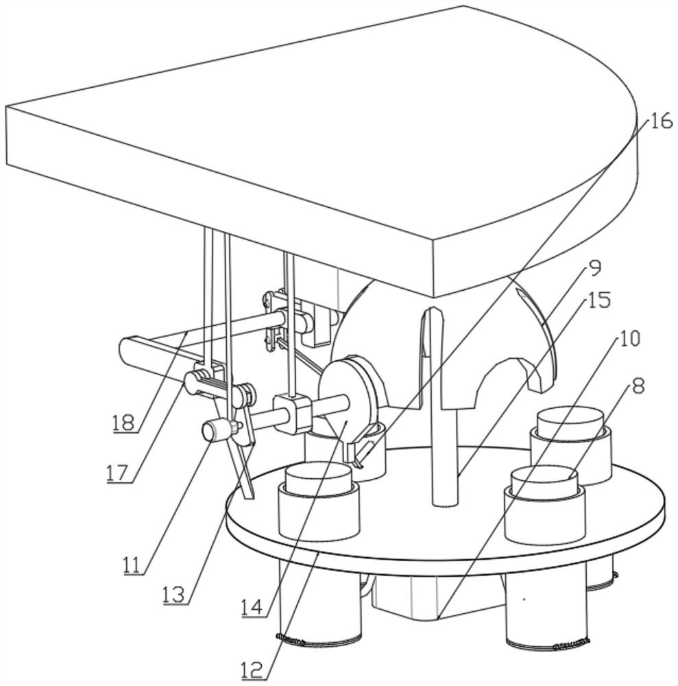
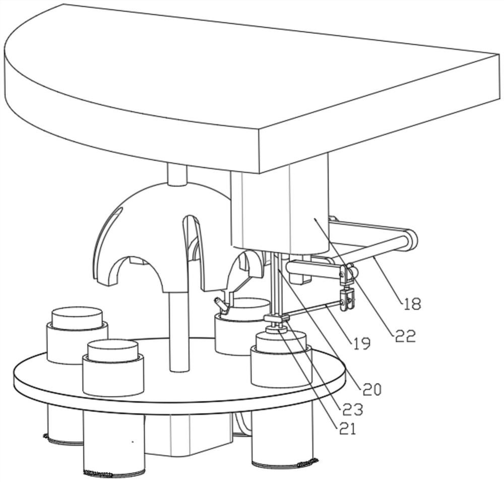
[0037] In this embodiment, the powder spreading mechanism includes a central rod 15 and a No. 2 motor 11, the upper end of the central rod 15 is rotatably arranged on the lower side of the upper top plate 4, and the central rod 15 is provided with a receiving ring 9 , the receiving ring 9 is provided with a circular groove and a vertical groove, the other end of the central rod 15 is provided with a turntable 12, and the turntable 12 is provided with a plurality of installation cylinders, which slide up and down to insert Connected with connecting cylinder 8.

[0038] The output end of the No. 2 motor 11 is connected with a mounting block, and the mounting block is fixed on the upper side of the upper top plate 4 through a fixed rod. The output end of the No. 2 motor 11 is connected with a rocker 13, and the...


PUM


Abstract

The invention relates to the field of pharmacy, and especially relates to a pharmaceutical mixing machine with an automatic feeding mechanism. The machine comprises a lower bottom plate, a plurality of supporting rods and a fixing mechanism are symmetrically arranged on the upper side of the lower bottom plate, an upper top plate is arranged at the other ends of the supporting rods, and a powder scattering mechanism is arranged on the lower side of the upper top plate. The powder scattering mechanism comprises a center plate and a second motor, the upper end of the center plate is rotationally arranged on the lower side of the upper top plate, a bearing ring is arranged on the center plate, a circular ring groove and a vertical groove are formed in the bearing ring, a rotating disc is arranged at the other end of the center plate, a plurality of mounting cylinders are arranged on the rotating disc, and the mounting cylinders are arranged on the rotating disc. A connecting cylinder is inserted into each mounting cylinder in an up-down sliding mode, and the output end of the second motor is connected with a mounting block. The mixing machine is scientific in structure, large-particle powder mixed in medicine powder can be effectively smashed in the medicine mixing process, the smashing effect is good, and the production efficiency is high.

Description

technical field [0001] The invention relates to the pharmaceutical field, in particular to a pharmaceutical mixer with an automatic feeding mechanism. Background technique [0002] In the production process of medicines, it is often necessary to mix a variety of medicines. At this time, a pharmaceutical mixer is needed. The pharmaceutical mixer can mix different kinds of medicines evenly, and then make the uniformly mixed medicine powder into tablets and pulverize them. [0003] The existing pharmaceutical mixers cannot effectively pulverize the large particle powder doped in the powder when stirring and mixing the powder, and the stirring effect cannot meet the production needs. [0004] Therefore, in view of the above current situation, there is an urgent need to develop a pharmaceutical mixer with an automatic feeding mechanism to overcome the deficiencies in current practical applications. Contents of the invention [0005] The object of the present invention is to pr...

Claims


Application Information

Patent Timeline
Patent Type & Authority Applications(China)
IPC IPC(8): B01F13/10B01F11/00B01F15/00B01F15/02
CPCB01F31/00B01F31/70B01F33/8305B01F35/123B01F35/42B01F35/3204B01F35/71B01F2101/22
Inventor 李元章
Owner 重庆天致药业股份有限公司
Why Eureka
Try Eureka