Supercharge Your Innovation With Domain-Expert AI Agents!

Core rod circulating moving heat preservation equipment and method for plate and strip hot coil box

A technology of hot coil boxes and mandrels, applied in metal processing equipment, metal rolling, manufacturing tools, etc., can solve problems such as the temperature drop of the strip, affecting the production of the next process of the strip, and the normal coiling of the strip, etc., to achieve Reduce the energy consumption of electric heating and reduce the effect of cutting and re-welding process

Pending Publication Date: 2021-08-10
CISDI RES & DEV CO LTD
View PDF0 Cites 0 Cited by
  • Summary
  • Abstract
  • Description
  • Claims
  • Application Information

AI Technical Summary

Problems solved by technology

[0002] The current hot coil box has the following problems in the application process: 1) At present, the general hot coil box can only coil hot-rolled strips with a thickness of 30-45mm and a maximum width of about 2300mm, and cannot coil thinner and / or wider strips 2) There is a problem of lowering the temperature of the strip when the hot coil box has a mandrel transfer; 3) When the hot coil box is coiled without a mandrel, the coil is formed due to the irregular shape of the head of the strip impacting the roller system (forming roller) or the guide plate. Eye, when the ultra-thin (thickness 1-30-60mm) ultra-wide (width 500-5500mm) strip forms a steel coil with an irregular size and shape (conical or elliptical cylinder, etc.), the strip will not be rolled normally The situation of picking, or quality accidents and other problems will affect the production of the next process of the strip

Method used


Image

  • Core rod circulating moving heat preservation equipment and method for plate and strip hot coil box
  • Core rod circulating moving heat preservation equipment and method for plate and strip hot coil box
  • Core rod circulating moving heat preservation equipment and method for plate and strip hot coil box

Examples


Embodiment Construction

[0031] Embodiments of the present invention are described below through specific examples, and those skilled in the art can easily understand other advantages and effects of the present invention from the content disclosed in this specification. The present invention can also be implemented or applied through other different specific implementation modes, and various modifications or changes can be made to the details in this specification based on different viewpoints and applications without departing from the spirit of the present invention. It should be noted that the diagrams provided in the following embodiments are only schematically illustrating the basic concept of the present invention, and the following embodiments and the features in the embodiments can be combined with each other in the case of no conflict.

[0032] Wherein, the accompanying drawings are for illustrative purposes only, and represent only schematic diagrams, rather than physical drawings, and should...


PUM

PropertyMeasurementUnit
thicknessaaaaaaaaaa
widthaaaaaaaaaa

Abstract

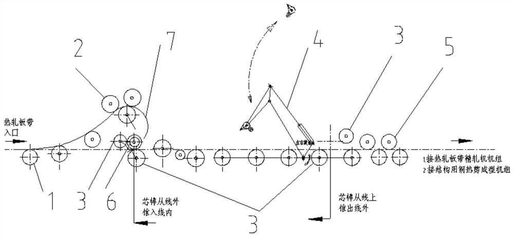
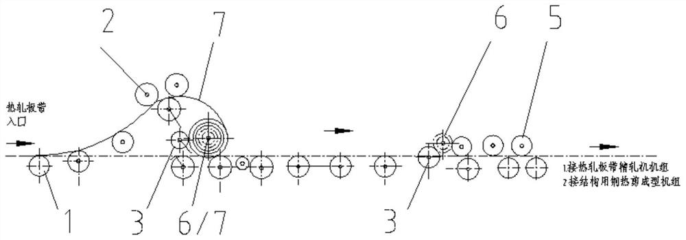
The invention belongs to the field of metallurgical machinery, and relates to core rod circulating moving heat preservation equipment and method for a plate and strip hot coil box. The equipment comprises a bending device, a core rod, a moving roller system, a core rod positioning bracket and a push cylinder, wherein the bending device is configured to coiling hot plates and strips, the core rod is configured to provide an axis for the plates and strips in the coiling process, the moving roller system is configured to fix, move and support the hot plates and strips and / or the core rod, the core rod positioning bracket is configured to provide outer side support for the hot plates and strips in the coiling process, and the push cylinder is configured to axially move the core rod. The problem that irregular roll holes are formed in the plates and strips is solved by circularly moving the core rod and providing a heat preservation heating mode, the coiled plates and strips can be used as finished products, the problem that the ultra-thin, ultra-wide and ultra-long plates and strips cannot be transported is solved, the working procedures of shearing and welding are reduced, and the product use of large special structures (buildings, bridges, ships and the like) is met.

Description

technical field [0001] The invention belongs to the field of metallurgical machinery, and relates to a heat preservation device and method for circularly moving mandrels of a strip hot coil box. Background technique [0002] The current hot coil box has the following problems in the application process: 1) At present, the general hot coil box can only coil hot-rolled strips with a thickness of 30-45mm and a maximum width of about 2300mm, and cannot coil thinner and / or wider strips 2) There is a problem of lowering the temperature of the strip when the hot coil box has a mandrel transfer; 3) When the hot coil box is coiled without a mandrel, the coil is formed due to the irregular shape of the head of the strip impacting the roller system (forming roller) or the guide plate. Eye, when the ultra-thin (thickness 1-30-60mm) ultra-wide (width 500-5500mm) strip forms a steel coil with an irregular size and shape (conical or elliptical cylinder, etc.), the strip will not be rolled ...

Claims


Application Information

Patent Timeline
Patent Type & Authority Applications(China)
IPC IPC(8): B21B15/00
CPCB21B15/00B21B2015/0057
Inventor 杨固川杨远平
Owner CISDI RES & DEV CO LTD
Features
  • R&D
  • Intellectual Property
  • Life Sciences
  • Materials
  • Tech Scout
  • Unparalleled Data Quality
  • Higher Quality Content
  • 60% Fewer Hallucinations
Learn More