Universal robot capable of self-adaptively crossing steps
What is AI technical title?
AI technical title is built by Patsnap AI team. It summarizes the technical point description of the patent document.
An adaptive and robotic technology, applied in the field of universal robots, can solve problems such as the inability to effectively cross and walk ladder-shaped obstacles, and achieve high stability
Active Publication Date: 2021-08-10
HARBIN INST OF TECH
View PDF12 Cites 0 Cited by
Summary
Abstract
Description
Claims
Application Information
AI Technical Summary
This helps you quickly interpret patents by identifying the three key elements:
Problems solved by technology
Method used
Benefits of technology
Problems solved by technology
[0005] The purpose of the present invention is to solve the problem that the existing obstacle-crossing chassis cannot realize the effective crossing and walking of stepped obstacles, and provides a universal robot that can self-adaptively cross the steps
Method used
Image
Click on the blue label to locate the original text in one second.
Reading with bidirectional positioning of images and text.
Examples
specific Embodiment approach 1
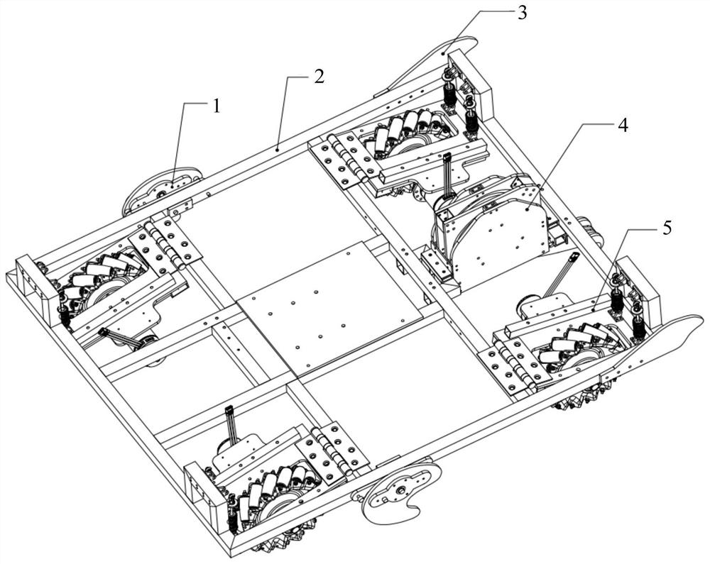
[0058] Specific implementation mode one: the following combination Figure 1-Figure 5Describe this embodiment mode, a universal robot that self-adaptively straddles the stairs described in this embodiment mode, it includes a rotating cam 1, a frame 2, a straightening plate 3, a pole vault mechanism 4 and a running mechanism 5;
[0059] The four traveling mechanisms 5 are installed on the four corners of the frame 2 respectively, and the two rotating cams 1 are installed on the sides of the frame 2 respectively, and are respectively located at the front ends of the two traveling mechanisms 5 at the rear, and the two righting plates 3 are installed on the frame 2, and are respectively located on the side of the two front running mechanisms 5, the pole vault mechanism 4 is installed inside the frame 2, and placed between the two front running mechanisms 5;
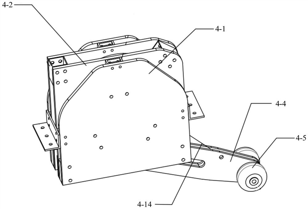
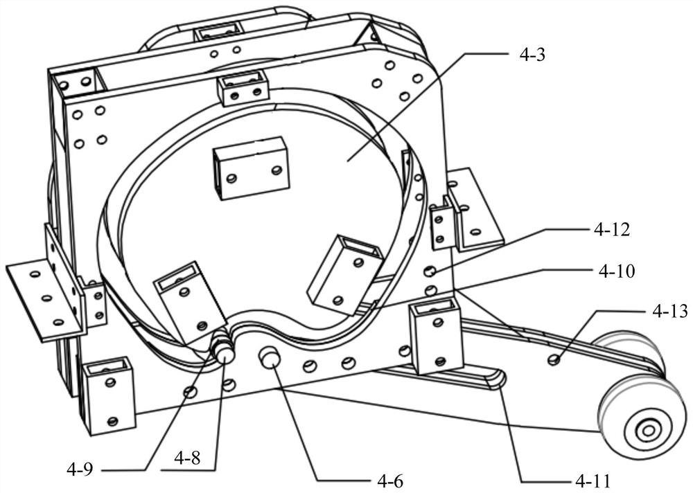
[0060] The pole vault mechanism 4 includes two fixed plates 4-1, two track outer plates 4-2, two track inner plates 4-3, su...
specific Embodiment approach 2
[0074] Specific implementation mode two: the following combination Figure 6-Figure 8 Describe this embodiment, this embodiment will further describe the first embodiment, the rotary cam 1 includes a cam plate 1-1, a first reinforcement plate 1-3, a second reinforcement plate 1-4, and a third reinforcement plate 1-5 and the fourth reinforcing plate 1-6;
[0075] The cam plate 1-1 is a "C" type structure, and the two sides of the cam plate 1-1 are respectively provided with a first reinforcing plate 1-3 and a second reinforcing plate 1-4, and the third bolt 1-2 passes through the first Reinforcement plate 1-3, cam plate 1-1, second reinforcement plate 1-4, third reinforcement plate 1-5, frame 2 and fourth reinforcement plate 1-6 are then screwed with nuts so that cam plate 1- 1 can freely rotate around the third bolt 1-2;
[0076] A fourth bolt 1-9 is arranged on the side of the cam plate 1-1 facing the frame 2, a fifth bolt 1-10 is arranged on the frame 2, and an elastic pul...
specific Embodiment approach 3
[0079] Specific implementation mode three: the following combination Image 6 with Figure 7 This embodiment will be described. This embodiment will further describe the second embodiment. The rotary cam 1 also includes a first flange bearing 1-7 and a second flange bearing 1-8.
[0080] The third bolt 1-2 passes through the first flange bearing 1-7, the first reinforcement plate 1-3, the cam plate 1-1, the second reinforcement plate 1-4, the second flange bearing 1-8, the Three reinforcing plates 1-5, a frame 2 and a fourth reinforcing plate 1-6.
PUM
Abstract
The invention discloses a universal robot capable of self-adaptively crossing stairs, belongs to the technical field of obstacle crossing robots, and aims to solve the problem that an existing obstacle crossingchassis cannot realize effective crossing and walking of stepped obstacles. The universal robot comprises a rotating cam, a frame, a straightening plate, a pole vault mechanism and a walking mechanism. According to the pole vault mechanism, inner track plates are circular plates with the bottoms concave inwards, outer track plates are annular plates, the outer edges of the annular plates are square, the inner edges of the annular plates are matched with the inner track plates, the outer track plates are fixedly connected, the outer track plates are fixedly connected with fixing plates, the inner track plates are fixedly connected with the fixing plates, and space curved grooves are formed between the outer track plates and the inner track plates. A first bolt is installed between the track outer plates and sleeved with a first bearing, the rear end of the supporting rod penetrates through the bolt, the bolt penetrates through the bearing, the bearing moves along the track of the curved groove in the space curved groove, a limiting groove is formed in the middle section of the supporting rod, and the first bearing is clamped in the limiting groove. The invention is used for a robotchassis with high requirements for obstacle crossing and flat ground speed.
Description
technical field [0001] The invention relates to a universal robot capable of self-adaptively stepping over stairs, belonging to the technical field of obstacle-surmounting robots. Background technique [0002] Due to its flexible mobility, intelligent robots are widely used in environments such as homes, communities or hospitals, and are mainly used for transportation, walking assistance or cleaning operations. When facing obstacles such as gravel and tiles, intelligent robots usually use obstacle avoidance or obstacle surmounting. [0003] Most of the existing obstacle-crossing chassis adopt crawler type, planetary wheel type (including active type and passive type), six-wheel type structure or lifting mechanism. Among them, the crawler chassis has good terrain adaptability and strong driving force, but due to its own weight, it is slow in speed and low in efficiency when driving on flat ground or over obstacles; there are structural comparisons between planetary wheel and...
Claims
Application Information
Patent Timeline
Application Date:The date an application was filed.
Publication Date:The date a patent or application was officially published.
First Publication Date:The earliest publication date of a patent with the same application number.
Issue Date:Publication date of the patent grant document.
PCT Entry Date:The Entry date of PCT National Phase.
Estimated Expiry Date:The statutory expiry date of a patent right according to the Patent Law, and it is the longest term of protection that the patent right can achieve without the termination of the patent right due to other reasons(Term extension factor has been taken into account ).
Invalid Date:Actual expiry date is based on effective date or publication date of legal transaction data of invalid patent.

