
Roller way replacing device for deformed steel rolling mill

A steel rolling mill and special-shaped technology, which is applied in the field of replacement roller table devices for special-shaped steel rolling mills, can solve the problems affecting the process requirements and rolling efficiency of the production line, affecting the production line capacity and rolling efficiency, and reducing the quality of the lower surface of the rolling piece. Improve equipment utilization and maintenance speed, improve surface quality, and reduce maintenance workload

Active Publication Date: 2020-09-04
DALIAN HUARUI HEAVY IND GRP CO LTD
View PDF8 Cites 0 Cited by
  • Summary
  • Abstract
  • Description
  • Claims
  • Application Information

AI Technical Summary

Problems solved by technology

Friction will also cause the quality of the lower surface of the rolled piece to decline, affecting the price of the finished product
At the same time, friction will also reduce the speed of the rolled piece in the rolling line, affecting the production capacity and rolling efficiency of the entire production line
[0005] (2) The idler roll type is used, although the friction is reduced to a certain extent, but the idler roll without motor drive will also reduce the running speed of the rolled piece in the rolling line, and even cause stacking of steel in severe cases, affecting the process of the entire production line requirements and rolling efficiency
[0006] (3) Whether it is in the form of a guide groove or an idler roller, the elevation is fixed and cannot be adjusted
When the rolled piece passes through, it will have a large impact on the guide groove or idler roller, which will affect the service life

Method used


Image

  • Roller way replacing device for deformed steel rolling mill
  • Roller way replacing device for deformed steel rolling mill
  • Roller way replacing device for deformed steel rolling mill

Examples


Embodiment Construction

[0036] It should be noted that, in the case of no conflict, the embodiments of the present invention and the features in the embodiments can be combined with each other. The present invention will be described in detail below with reference to the accompanying drawings and examples.

[0037] In order to make the purpose, technical solutions and advantages of the embodiments of the present invention clearer, the technical solutions in the embodiments of the present invention will be clearly and completely described below in conjunction with the drawings in the embodiments of the present invention. Obviously, the described embodiments It is only some embodiments of the present invention, but not all embodiments. The following description of at least one exemplary embodiment is merely illustrative in nature and in no way taken as limiting the invention, its application or uses. Based on the embodiments of the present invention, all other embodiments obtained by persons of ordina...


PUM


Abstract

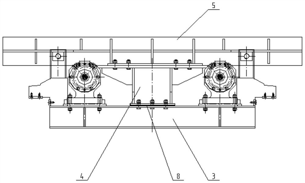
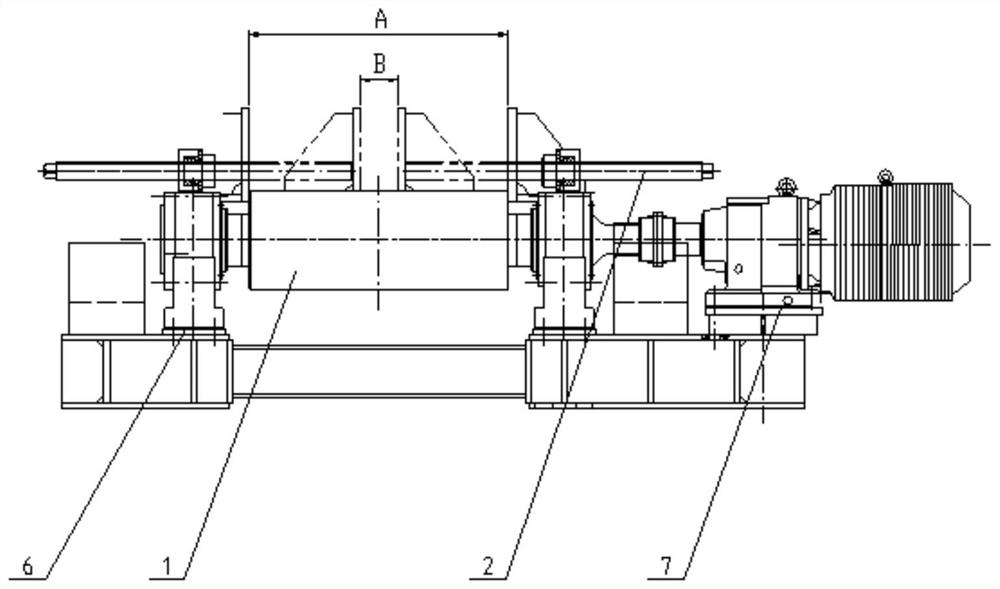
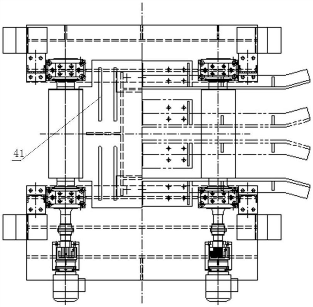
The invention provides a roller way replacing device for a deformed steel rolling mill. The roller way replacing device comprises a roller way frame, wherein driving roller devices of which the axes extend forwards and backwards are symmetrically mounted on the roller way frame left and right; a cover plate connected with the roller way frame through bolts is mounted between the two driving rollerdevices; side guide plates extending left and right are symmetrically mounted on the cover plate front and back; and jacking bar device groups are symmetrically mounted at the left end and the rightend of the roller way frame, and each jacking bar device group comprises two jacking bar devices which are symmetrical front and back. According to the roller way replacing device, the vacancy after the rolling mill is moved out is filled up by adopting a driving roller way type, the problem that a large number of guide groove spare parts are needed due to excessive impact of a rolled piece is solved, meanwhile, rolling friction is adopted between the rolled piece and rollers, and sliding friction is replaced by rolling friction, so that the surface quality of the rolled piece is greatly improved; and the roller way replacing device is simple in structure, adopts an offline adjusting mode, is low in failure rate, small in maintenance workload and simple to maintain, so that the productionefficiency is greatly improved.

Description

technical field [0001] The invention relates to the technical field of a special-shaped steel production line, in particular to a replacement roller table device for a special-shaped steel rolling mill. Background technique [0002] The replacement roller table is one of the important equipment in the special-shaped steel production line. The special-shaped steel production line has complicated technology and many types of products. When the rolling process is different or the products are different, one or more rolling mills in the rolling mill do not need to work. Sometimes it is necessary to remove the entire rolling mill from the rolling line. After the removal, there will be about 3 meters of space left in the original rolling mill position. At this time, it is necessary to replace the roller table and put it in the rolling mill position to fill the vacancy of the rolling mill to prevent steel from falling. [0003] The traditional technology uses a guide groove mechani...

Claims


Application Information

Patent Timeline
Patent Type & Authority Applications(China)
IPC IPC(8): B21B39/02B21B39/12B21B39/14
CPCB21B39/02B21B39/12B21B39/14Y02P70/10
Inventor 王磊马江涛吴含王刚宫代伟李大伟
Owner DALIAN HUARUI HEAVY IND GRP CO LTD
Learn More