A skeleton coil winding and hanging device

A skeleton coil, winding technology, applied in coil manufacturing, inductor/transformer/magnet manufacturing, electrical components, etc., can solve the problem of inconvenient hanging, easy to hit the winding mold or rotating shaft 3, reducing winding efficiency, etc. problems, to achieve the effect of improving the hanging speed and production efficiency, reducing the risk of hand being hit, and improving the yield

Active Publication Date: 2022-07-08
浙江创特新材科技有限公司
View PDF3 Cites 0 Cited by
  • Summary
  • Abstract
  • Description
  • Claims
  • Application Information

AI Technical Summary

Problems solved by technology

[0004] When hanging the thread manually, because the distance between the wire groove 3-3 and the buckle is relatively short, the distance between the buckle and the rotating shaft 3 is relatively short, and the staff's hand speed is relatively fast, so when hanging the wire to the wire groove 3-3 The staff's hands are easy to rub against the buckle, and when hanging the wire to the buckle, the staff's hand is easy to hit the winding mold or the rotating shaft 3, which will cause the staff's hand to be injured, and it is easy to cause the positioning piece to be deformed and unusable. The positioning piece has to be replaced frequently, which reduces the winding efficiency
In addition, because the size of the wire slot 3-3 is small, it is necessary to align the wire slot 3-3 to put the enameled wire 4 into the wire slot 3-3, which is inefficient and inconvenient to hang the wire

Method used


Image

  • A skeleton coil winding and hanging device
  • A skeleton coil winding and hanging device
  • A skeleton coil winding and hanging device

Examples


Embodiment 1

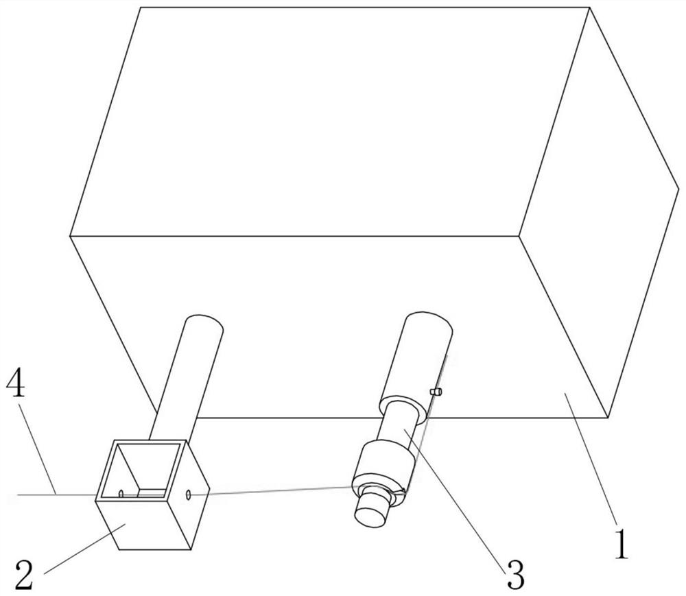
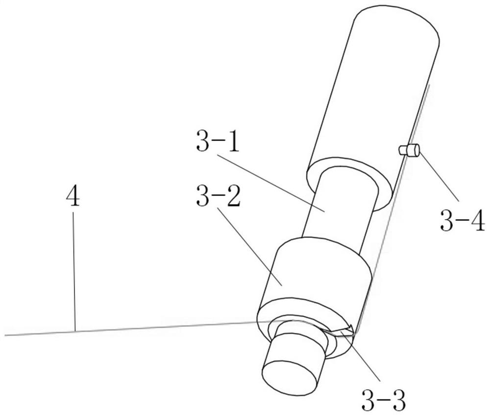
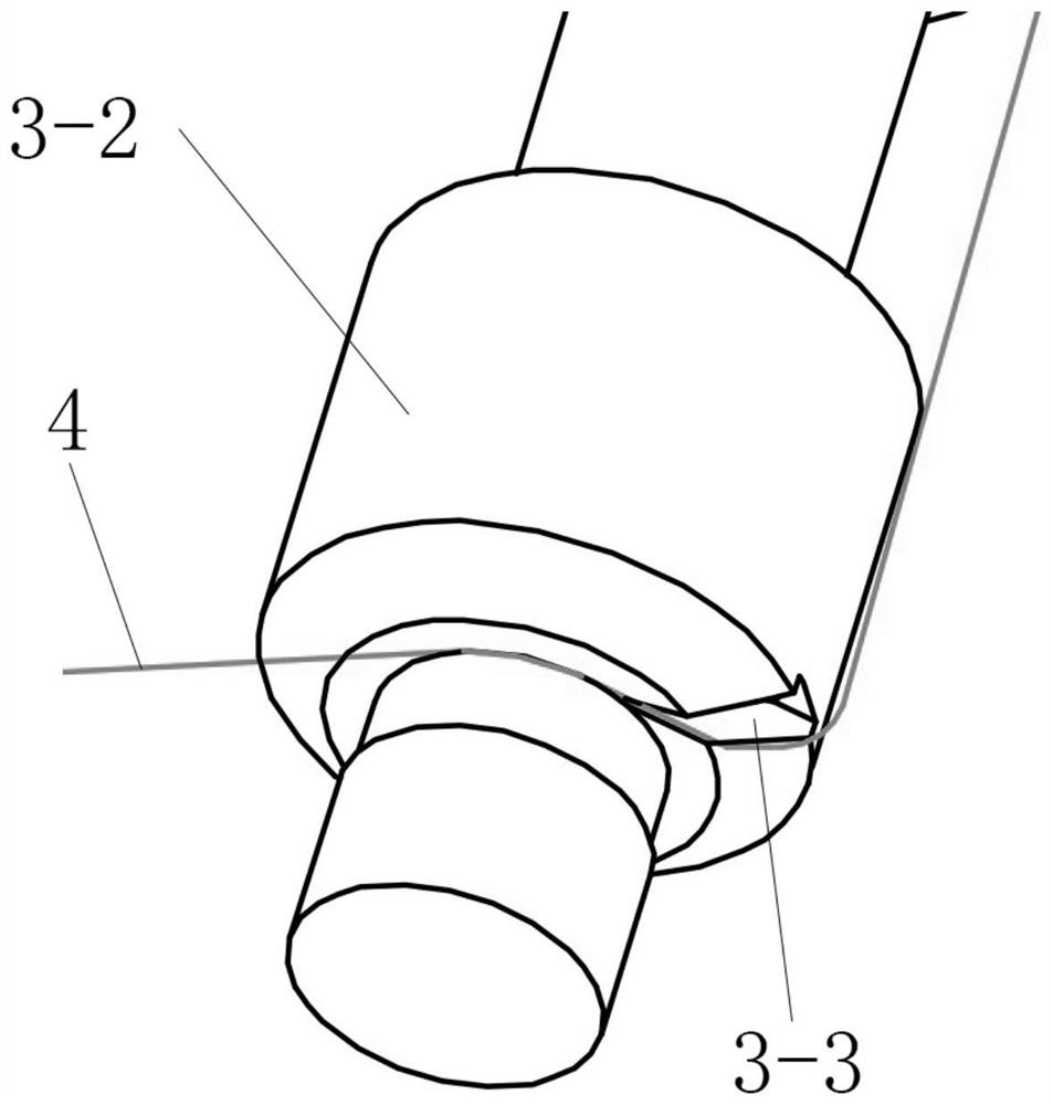
[0033] like Figure 4 , Figure 5 , Image 6 , Figure 7 Shown is one of the embodiments of the present invention. In this embodiment, a bobbin coil winding and hanging device is disclosed, including a main body 1, a driving device is arranged inside the main body 1, and a solvent box 2 and a solvent box 2 and Rotating shaft 3, the solvent box 2 is usually provided with alcohol cotton, the rotating shaft 3 is driven to rotate by the driving device, the enameled wire 4 is extended to the rotating shaft 3 through the solvent box 2, and the rotating shaft 3 is provided with a shaft sleeve 3-2, the shaft sleeve 3-2 is a part of the winding die, the sleeve 3-2 is provided with a wire slot 3-3, the rotating shaft 3 is also provided with a wire hanging disc 5, and the outer circumferential surface of the wire hanging disc 5 is provided with a positioning piece 5-3. The enameled wire 4 passes through the wire slot 3-3 and is positioned below the positioning piece 5-3.

[0034] By ...

Embodiment 2

[0051] like Figure 8 Shown is Embodiment 2 of the present invention. Different from Embodiment 1, the positioning surface 5-5 intersects the axis of the thread-hanging disk 5, and the intersection belongs to the intersection of a straight line and a plane in three-dimensional geometry.

[0052] When the positioning piece 5-3 is fixed with this design, the positioning piece 5-3 faces the staff, and it is more convenient to hang the enameled wire 4 under the positioning piece 5-3.

[0053] from Figure 8 It can also be seen that three positioning surfaces 5-5 are provided on the outer circumferential surface of the thread hanging disc 5, and three positioning pieces 5-3 can be fixed. If there is a problem with one of the positioning pieces 5-3, the other positioning pieces 5-3 can be used, which prolongs the service time of the wire hanging disc 5, and avoids the need to replace the positioning pieces 5-3 immediately, which will delay the work process.


PUM

PropertyMeasurementUnit
diameteraaaaaaaaaa

Abstract

The invention discloses a bobbin coil winding and hanging device, which solves the technical problems of poor safety and low winding efficiency of the existing manual winding machine. The skeleton coil winding and hanging device includes a main engine, a solvent box and a rotating shaft are arranged at the front of the main engine, the enameled wire is extended to the rotating shaft through the solvent box, and a shaft sleeve is arranged on the rotating shaft , the shaft sleeve is provided with a wire groove, the rotating shaft is also provided with a wire hanging disc, the outer circumferential surface of the wire hanging disc is provided with a positioning piece, and the enameled wire passes through the wire groove and is positioned at the below the positioning tab. The invention increases the distance between the positioning piece and the wire groove, the winding die or the rotating shaft by arranging the wire hanging disc on the rotating shaft, and the positioning piece is arranged on the circumferential surface of the wire hanging disc, and effectively avoids work The hands of the personnel collided, and the winding efficiency was improved at the same time.

Description

technical field [0001] The invention relates to the field of electroacoustic product manufacturing equipment, in particular to a bobbin coil winding and hanging device. Background technique [0002] The manual winding machine is a production equipment used for the winding process of the bobbin coil. The enameled wire can be wound on the coil bobbin through the manual winding machine. The circular bobbin coil winding process needs to be manually hung when winding, and each coil needs to be hung once. The hanging becomes a key action for coil yield and efficiency. [0003] The partial structure of the manual winding machine in the prior art is as follows: figure 1 , figure 2 , image 3 As shown, it includes the main engine 1, the main engine 1 is provided with a driving device, the front part of the main engine 1 is provided with a solvent box 2 and a rotating shaft 3, the solvent box 2 is usually provided with alcohol cotton, the rotating shaft 3 is driven and rotated by ...

Claims


Application Information

Patent Timeline
Patent Type & Authority Patents(China)
IPC IPC(8): H01F41/082H01F41/098H01F41/06
CPCH01F41/082H01F41/098H01F41/06
Inventor 张卫聂世连杨传涛
Owner 浙江创特新材科技有限公司
Why Eureka
Try Eureka